Product Description
Product Description
MAIN FEATURES:
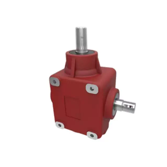
1) Made of high quality material, non-rusting;Both flange and foot mounting available and suitable for all-round installation
2) Large output torque and high radiating efficiency
3)Precise grinding helical gear with Smooth running and low noise, no deformation,can work long time in dreadful condition
4)Nice appearance, durable service life and small volume, compact structure
5)Both 2 and 3 stage available with wide ratio range from 5 to 200
6)Different output shaft diameter available -40-50mm
7)Modular construction enlarge ratio from 5 to 1400
MAIN MATERIALS:
1)housing with aluminium alloyand cast iron material;
2)Output Shaft Material:20CrMnTi
3)Good quality no noise bearings to keep long service life
4)High performance oil seal to prevent from oil leakage
APPLICATIONS:
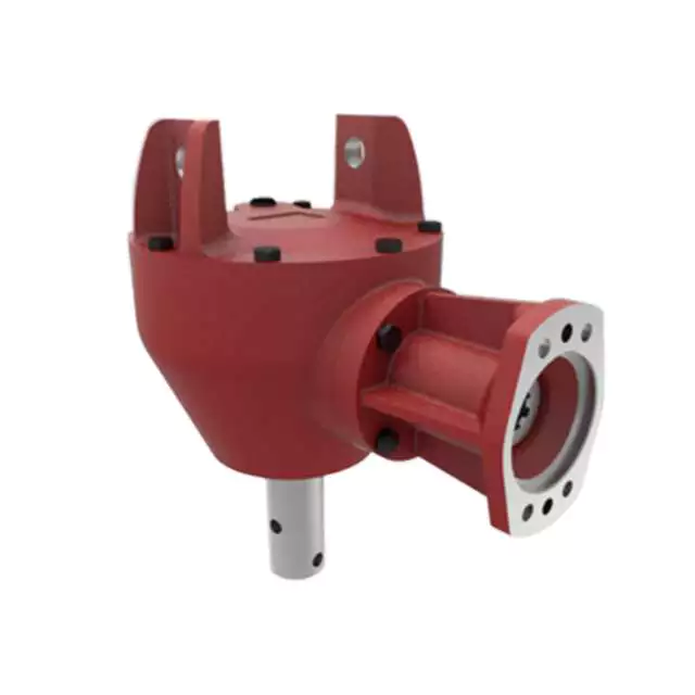
G3 Series helical gear motor are wide used for all kinds of automatic equipment, such as chip removal machine, conveyor, packaging equipment, woodworking machinery, farming equipment, slurry scraper ,dryer, mixer and so on.
Detailed Photos
Product Parameters
| (n1=1400r/min 50hz) | |||||||||||||||||
| norminal ratio | 5 | 10 | 15 | 20 | 25 | 30 | 40 | 50 | 60 | 80 | 100 | 100 | 120 | 160 | 200 | ||
| 0.1kw | output shaft | Ø18 | Ø22 | ||||||||||||||
| n2* (r/min) | 282 | 138 | 92 | 70 | 56 | 46 | 35 | 28 | 23 | 18 | 14 | – | 11 | 9 | 7 | ||
| M2(Nm) | 50hz | 3.2 | 6.5 | 9.8 | 12.9 | 16.1 | 19.6 | 25.7 | 31.1 | 37.5 | 49.5 | 62.9 | – | 76.1 | 100.7 | 125.4 | |
| 60hz | 3 | 5 | 8 | 11 | 13 | 17 | 21 | 26 | 31 | 41 | 52 | – | 63 | 84 | 105 | ||
| Fr1(N) | 588 | 882 | 980 | 1180 | 1270 | 1370 | 1470 | 1570 | 2160 | 2450 | 2450 | 2450 | 2450 | 2450 | 2450 | ||
| Fr2(N) | 176 | ||||||||||||||||
| norminal ratio | 5 | 10 | 15 | 20 | 25 | 30 | 40 | 50 | 60 | 80 | 100 | 100 | 120 | 160 | 200 | ||
| 0.2kw | output shaft | Ø18 | Ø22 | Ø28 | |||||||||||||
| n2* (r/min) | 282 | 138 | 92 | 70 | 56 | 45 | 35 | 29 | 23 | 18 | 14 | 13 | 12 | 8 | 7 | ||
| M2(Nm) | 50hz | 6.5 | 12.6 | 19.1 | 26.3 | 32.6 | 38.9 | 50.4 | 63 | 75.6 | 100.8 | 103.9 | 125.4 | 150 | 200.4 | 250.7 | |
| 60hz | 5.4 | 10.5 | 16.6 | 21.9 | 27.1 | 32.4 | 42 | 52.5 | 63 | 84 | 86.6 | 104.5 | 125 | 167 | 208.9 | ||
| Fr1(N) | 588 | 882 | 980 | 1180 | 1270 | 1760 | 1860 | 1960 | 2160 | 2450 | 2450 | 2840 | 3330 | 3430 | 3430 | ||
| Fr2(N) | 196 | ||||||||||||||||
| norminal ratio | 5 | 10 | 15 | 20 | 25 | 30 | 40 | 50 | 60 | 80 | 100 | 100 | 120 | 160 | 200 | ||
| 0.4kw | output shaft | Ø22 | Ø28 | Ø32 | |||||||||||||
| n2* (r/min) | 288 | 144 | 92 | 72 | 58 | 47 | 36 | 29 | 24 | 18 | 14 | 14 | 12 | 9 | 7 | ||
| M2(Nm) | 50hz | 12.9 | 25 | 38.6 | 51.4 | 65.4 | 78.2 | 100.7 | 125.4 | 150 | 200.4 | 206.8 | 250.7 | 301.1 | 400.7 | 461.8 | |
| 60hz | 10.7 | 20.8 | 32.1 | 42.9 | 54.5 | 65.2 | 83.9 | 104.5 | 125 | 167 | 172.3 | 208.9 | 250.9 | 333.9 | 384.8 | ||
| Fr1(N) | 882 | 1180 | 1370 | 1470 | 1670 | 2550 | 2840 | 3140 | 3430 | 3430 | 3430 | 4900 | 5880 | 5880 | 5880 | ||
| Fr2(N) | 245 | ||||||||||||||||
| norminal ratio | 5 | 10 | 15 | 20 | 25 | 30 | 40 | 50 | 60 | 80 | 100 | 100 | 120 | 160 | 200 | ||
| 0.75kw | output shaft | Ø28 | Ø32 | Ø40 | |||||||||||||
| n2* (r/min) | 278 | 140 | 94 | 69 | 58 | 46 | 35 | 29 | 24 | 18 | 14 | 14 | 11 | 9 | 7 | ||
| M2(Nm) | 50hz | 24.6 | 48.2 | 72.9 | 97.5 | 122.1 | 145.7 | 187.5 | 235.7 | 282.9 | 376.1 | 387.9 | 439 | 527 | 703 | 764 | |
| 60hz | 20.5 | 40.2 | 60.7 | 81.3 | 201.8 | 121.4 | 156.3 | 196.4 | 235.7 | 313.4 | 323.2 | 366 | 439 | 585 | 732 | ||
| Fr1(N) | 1270 | 1760 | 2160 | 2350 | 2450 | 4571 | 4210 | 4610 | 5490 | 5880 | 5880 | 7060 | 7060 | 7060 | 7060 | ||
| Fr2(N) | 294 | ||||||||||||||||
| norminal ratio | 5 | 10 | 15 | 20 | 25 | 30 | 40 | 50 | 60 | 80 | 100 | 100 | 120 | 160 | 200 | ||
| 1.5kw | output shaft | Ø32 | Ø40 | Ø50 | |||||||||||||
| n2* (r/min) | 280 | 140 | 93 | 70 | 55 | 47 | 34 | 27 | 24 | 17 | 14 | 13 | 12 | 8 | 7 | ||
| M2(Nm) | 50hz | 48.2 | 97.5 | 145.7 | 193.9 | 242.1 | 272 | 351 | 439 | 527 | 703 | 724 | 878 | 1060 | 1230 | 1230 | |
| 60hz | 40.2 | 81.3 | 121.4 | 161.6 | 201.8 | 226 | 293 | 366 | 439 | 585 | 603 | 732 | 878 | 1170 | 1230 | ||
| Fr1(N) | 1760 | 2450 | 2840 | 3230 | 3820 | 5100 | 5880 | 7060 | 7060 | 7060 | 7060 | 9800 | 9800 | 9800 | 9800 | ||
| Fr2(N) | 343 | ||||||||||||||||
| norminal ratio | 5 | 10 | 15 | 20 | 25 | 30 | 40 | 50 | 60 | 80 | 100 | ||||||
| 2.2kw | output shaft | Ø40 | Ø50 | ||||||||||||||
| n2* (r/min) | 272 | 136 | 95 | 68 | 54 | 45 | 36 | 28 | 24 | 18 | 14 | ||||||
| M2(Nm) | 50hz | 67 | 133 | 200 | 266 | 332 | 399 | 515 | 644 | 773 | 1571 | 1230 | |||||
| 60hz | 56 | 111 | 167 | 221 | 277 | 332 | 429 | 537 | 644 | 858 | 1080 | ||||||
| Fr1(N) | 2160 | 3140 | 3530 | 4571 | 4700 | 6960 | 7250 | 8620 | 9800 | 9800 | 9800 | ||||||
| Fr2(N) | 392 | ||||||||||||||||
Outline and mounting dimension:
| G3FM: THREE PHASE GEAR MOTOR WITH FLANGE (n1=1400r/min) | ||||||||||||||||||||
| Power kw | output shaft | ratio | A | F | I | J | M | O | O1 | P | Q | R | S | T | U | W | X | Y | Y1 | |
| standard | brake | |||||||||||||||||||
| 0.1kw | Ø18 | 5–30-40-50 | 236 | 270 | 192.5 | 11 | 16.5 | 170 | 4 | 10 | 30 | 145 | 35 | 18 | 20.5 | 129 | 6 | 157 | 80 | 81 |
| Ø22 | -160-200 | 262 | 296 | 197.5 | 11 | 19 | 185 | 4 | 12 | 40 | 148 | 47 | 22 | 24.5 | 129 | 6 | 171.5 | 89.5 | 83.5 | |
| 0.2kw | Ø18 | 5- | 267 | 270 | 192.5 | 11 | 16.5 | 170 | 4 | 10 | 30 | 145 | 35 | 18 | 20.5 | 129 | 6 | 161 | 80 | 81 |
| Ø22 | -80-100 | 293 | 296 | 197.5 | 11 | 19 | 185 | 4 | 12 | 40 | 148 | 47 | 22 | 24.5 | 129 | 6 | 171.5 | 89.5 | 83.5 | |
| Ø28 | 306 | 309.5 | 208.5 | 11 | 23.5 | 215 | 4 | 15 | 45 | 170 | 50 | 28 | 31 | 129 | 8 | 198.5 | 105.5 | 88 | ||
| 0.4kw | Ø22 | 5- | 314 | 324.5 | 204 | 11 | 19 | 185 | 4 | 12 | 40 | 148 | 47 | 22 | 24.5 | 139 | 6 | 171.5 | 89.5 | 88.5 |
| Ø28 | -80-100 | 330 | 337.5 | 215 | 11 | 23.5 | 215 | 4 | 15 | 45 | 170 | 50 | 28 | 31 | 139 | 8 | 198.5 | 105.5 | 93 | |
| Ø32 | 349 | 357 | 229.5 | 13 | 28.5 | 250 | 4 | 15 | 55 | 180 | 60 | 32 | 35 | 139 | 10 | 234 | 126 | 98 | ||
| 0.75kw | Ø28 | 5- | 350.5 | 343.5 | 227.5 | 11 | 23.5 | 215 | 4 | 15 | 45 | 170 | 50 | 28 | 31 | 159 | 8 | 198.5 | 105.5 | 103 |
| Ø32 | -80-100 | 379.5 | 387 | 242 | 13 | 28.5 | 250 | 4 | 15 | 55 | 180 | 60 | 32 | 35 | 159 | 10 | 234 | 126 | 108 | |
| Ø40 | 401.5 | 408.5 | 270 | 18 | 34 | 310 | 5 | 18 | 65 | 230 | 71 | 40 | 43 | 185 | 12 | 284 | 149 | 126.5 | ||
| 1.5kw | Ø32 | 5- | 420.5 | 441 | 254 | 13 | 28.5 | 250 | 5 | 15 | 55 | 180 | 60 | 32 | 35 | 185 | 10 | 234 | 126 | 121 |
| Ø40 | -80-100 | 457.5 | 478 | 270 | 18 | 34 | 310 | 5 | 18 | 65 | 230 | 71 | 40 | 43 | 185 | 12 | 284 | 149 | 126.5 | |
| Ø50 | 485.5 | 506 | 300 | 22 | 40 | 360 | 5 | 25 | 75 | 270 | 83 | 50 | 53.5 | 185 | 14 | 325 | 173.5 | 132.5 | ||
| 2.2kw | Ø40 | 5- | 466.5 | 487 | 270 | 18 | 34 | 310 | 5 | 18 | 65 | 230 | 71 | 40 | 43 | 185 | 12 | 284 | 149 | 126.5 |
| Ø50 | -80-100 | 510.5 | 531 | 300 | 22 | 40 | 360 | 5 | 25 | 75 | 270 | 83 | 50 | 53.5 | 185 | 14 | 325 | 173.5 | 132.5 | |
| G3LM: THREE PHASE GEAR MOTOR WITH FOOT (n1=1400r/min) | ||||||||||||||||||||
| Power kw | output shaft | ratio | A | D | E | F | J | G | H | K | P | S | T | U | V | W | X | Y | Y1 | |
| standard | brake | |||||||||||||||||||
| 0.1kw | Ø18 | 5–30-40-50 | 236 | 270 | 40 | 110 | 135 | 16.5 | 65 | 9 | 45 | 30 | 18 | 20.5 | 129 | 183 | 6 | 133 | 85 | 10 |
| Ø22 | -160-200 | 262 | 296 | 65 | 130 | 155 | 19 | 90 | 11 | 55 | 40 | 22 | 24.5 | 129 | 193 | 6 | 139.5 | 90 | 12 | |
| 0.2kw | Ø18 | 5- | 267 | 270 | 40 | 110 | 135 | 16.5 | 65 | 9 | 45 | 30 | 18 | 20.5 | 129 | 183 | 6 | 133 | 85 | 10 |
| Ø22 | -80-100 | 293 | 296 | 65 | 130 | 155 | 19 | 90 | 11 | 55 | 40 | 22 | 24.5 | 129 | 193 | 6 | 139.5 | 90 | 12 | |
| Ø28 | 306 | 309.5 | 90 | 140 | 175 | 23.5 | 125 | 11 | 65 | 45 | 28 | 31 | 129 | 203 | 8 | 170 | 110 | 15 | ||
| 0.4kw | Ø22 | 5- | 314 | 324.5 | 65 | 130 | 155 | 19 | 90 | 11 | 55 | 40 | 22 | 24.5 | 139 | 199.5 | 6 | 141.5 | 90 | 12 |
| Ø28 | -80-100 | 330 | 337.5 | 90 | 140 | 175 | 23.5 | 125 | 11 | 65 | 45 | 28 | 31 | 139 | 210 | 8 | 170 | 110 | 15 | |
| Ø32 | 349 | 357 | 130 | 170 | 208 | 28.5 | 170 | 13 | 70 | 55 | 32 | 35 | 139 | 226 | 10 | 198 | 130 | 18 | ||
| 0.75kw | Ø28 | 5- | 350.5 | 343.5 | 90 | 140 | 175 | 23.5 | 125 | 11 | 65 | 45 | 28 | 31 | 159 | 222 | 8 | 170 | 110 | 15 |
| Ø32 | -80-100 | 379.5 | 387 | 130 | 170 | 208 | 28.5 | 170 | 13 | 70 | 55 | 32 | 35 | 159 | 238.5 | 10 | 198 | 130 | 18 | |
| Ø40 | 401.5 | 408.5 | 150 | 210 | 254 | 34 | 196 | 15 | 90 | 65 | 40 | 43 | 185 | 249 | 12 | 230 | 150 | 20 | ||
| 1.5kw | Ø32 | 5- | 420.5 | 441 | 130 | 170 | 208 | 28.5 | 170 | 13 | 70 | 55 | 32 | 35 | 185 | 250.5 | 10 | 198 | 130 | 18 |
| Ø40 | -80-100 | 457.5 | 478 | 150 | 210 | 254 | 34 | 196 | 15 | 90 | 65 | 40 | 43 | 185 | 260 | 12 | 230 | 150 | 20 | |
| Ø50 | 485.5 | 506 | 160 | 230 | 290 | 40 | 210 | 18 | 100 | 75 | 50 | 53.5 | 185 | 288 | 14 | 265 | 170 | 25 | ||
| 2.2kw | Ø40 | 5- | 466.5 | 487 | 150 | 210 | 254 | 34 | 196 | 15 | 90 | 65 | 40 | 43 | 185 | 260 | 12 | 230 | 150 | 20 |
| Ø50 | -80-100 | 510.5 | 531 | 160 | 230 | 290 | 40 | 210 | 18 | 100 | 75 | 50 | 53.5 | 185 | 288 | 14 | 265 | 170 | 25 | |
| G3FS: IEC GEAR REDUCER WITH FOOT (n1=1400r/min) | |||||||||||||||||||||||||
| Power kw | output shaft | ratio | A | B | C | F | I | J | L | M | N | O | O1 | P | Q | R | S | S1 | T | T1 | W | W1 | X | Y | Y1 |
| 0.12kw | Ø18 | 5–30-40-50 | 147 | 95 | 115 | 154 | 11 | 16.5 | 4.5 | 170 | 140 | 4 | 10 | 30 | 145 | 35 | 18 | 11 | 20.5 | 12.8 | 6 | 4 | 163 | 80 | 86.5 |
| Ø22 | -160-200 | 173 | 95 | 115 | 164 | 11 | 19 | 4.5 | 185 | 140 | 4 | 12 | 40 | 148 | 47 | 22 | 11 | 24.5 | 12.8 | 6 | 4 | 171.5 | 89.5 | 89 | |
| 0.18kw | Ø18 | 5- | 147 | 95 | 115 | 154 | 11 | 16.5 | 4.5 | 170 | 140 | 4 | 10 | 30 | 145 | 35 | 18 | 11 | 20.5 | 12.8 | 6 | 4 | 163 | 80 | 86.5 |
| Ø22 | -80-100 | 173 | 95 | 115 | 164 | 11 | 19 | 4.5 | 185 | 140 | 4 | 12 | 40 | 148 | 47 | 22 | 11 | 24.5 | 12.8 | 6 | 4 | 171.5 | 89.5 | 89 | |
| Ø28 | 186.5 | 95 | 115 | 186 | 11 | 23.5 | 4.5 | 215 | 140 | 4 | 15 | 45 | 170 | 50 | 28 | 11 | 31 | 12.8 | 8 | 4 | 198.5 | 105.5 | 93.5 | ||
| 0.37kw | Ø22 | 5- | 181.5 | 110 | 130 | 164 | 11 | 19 | 4.5 | 185 | 160 | 4 | 12 | 40 | 148 | 47 | 22 | 14 | 24.5 | 16.3 | 6 | 5 | 201 | 89.5 | 99 |
| Ø28 | -80-100 | 198 | 110 | 130 | 186 | 11 | 23.5 | 4.5 | 215 | 160 | 4 | 15 | 45 | 170 | 50 | 28 | 14 | 31 | 16.3 | 8 | 5 | 198.5 | 105.5 | 103.5 | |
| Ø32 | 216.5 | 110 | 130 | 215 | 13 | 28.5 | 4.5 | 250 | 160 | 4 | 15 | 55 | 180 | 60 | 32 | 14 | 35 | 16.3 | 10 | 5 | 234 | 126 | 108.5 | ||
| 0.75kw | Ø28 | 5- | 206.5 | 130 | 165 | 185 | 11 | 23.5 | 4.5 | 215 | 200 | 4 | 15 | 45 | 170 | 50 | 28 | 19 | 31 | 21.8 | 8 | 6 | 216.5 | 105.5 | 123.5 |
| Ø32 | -80-100 | 235 | 130 | 165 | 215 | 13 | 28.5 | 4.5 | 250 | 200 | 4 | 15 | 55 | 180 | 60 | 32 | 19 | 35 | 21.8 | 10 | 6 | 236.5 | 126 | 128.5 | |
| Ø40 | 260.5 | 130 | 165 | 270 | 18 | 34 | 4.5 | 310 | 200 | 5 | 18 | 65 | 230 | 71 | 40 | 19 | 43 | 21.8 | 12 | 8 | 284 | 149 | 134 | ||
| 1.5kw | Ø32 | 5- | 252 | 130 | 165 | 215 | 13 | 28.5 | 4.5 | 250 | 200 | 5 | 15 | 55 | 180 | 60 | 32 | 24 | 35 | 27.3 | 10 | 8 | 236.5 | 126 | 128.5 |
| Ø40 | -80-100 | 293.5 | 130 | 165 | 270 | 18 | 34 | 4.5 | 310 | 200 | 5 | 18 | 65 | 230 | 71 | 40 | 24 | 43 | 27.3 | 12 | 8 | 284 | 149 | 134 | |
| Ø50 | 321.5 | 130 | 165 | 300 | 22 | 40 | 4.5 | 360 | 200 | 5 | 25 | 75 | 270 | 83 | 50 | 24 | 53.5 | 27.3 | 14 | 8 | 323.5 | 173.5 | 140 | ||
| 2.2kw | Ø40 | 5- | 290 | 180 | 215 | 270 | 18 | 34 | 5.5 | 310 | 250 | 5 | 18 | 65 | 230 | 71 | 40 | 28 | 43 | 31.3 | 12 | 8 | 284 | 149 | 134 |
| Ø50 | -80-100 | 334 | 180 | 215 | 300 | 22 | 40 | 5.5 | 360 | 250 | 5 | 25 | 75 | 270 | 83 | 50 | 28 | 53.5 | 31.3 | 14 | 8 | 323.5 | 173.5 | 140 | |
| G3LS: IEC GEAR REDUCER WITH FOOT (n1=1400r/min) | |||||||||||||||||||||||||
| Power kw | output shaft | ratio | A | B | C | D | E | F | G | H | J | K | L | N | P | S | S1 | T | T1 | W | W1 | X | Y | Y1 | Z |
| 0.12kw | Ø18 | 5–30-40-50 | 147 | 95 | 115 | 40 | 110 | 135 | 65 | 9 | 16.5 | 45 | 4.5 | 140 | 30 | 18 | 11 | 20.5 | 12.8 | 6 | 4 | 138.5 | 85 | 10 | M8 |
| Ø22 | -160-200 | 173 | 95 | 115 | 65 | 130 | 154 | 90 | 11 | 19 | 55 | 4.5 | 140 | 40 | 22 | 11 | 24.5 | 12.8 | 6 | 4 | 141 | 90 | 12 | M8 | |
| 0.18kw | Ø18 | 5- | 147 | 95 | 115 | 40 | 110 | 135 | 65 | 9 | 16.5 | 45 | 4.5 | 140 | 30 | 18 | 11 | 20.5 | 12.8 | 6 | 4 | 138.5 | 85 | 10 | M8 |
| Ø22 | -80-100 | 173 | 95 | 115 | 65 | 130 | 154 | 90 | 11 | 19 | 55 | 4.5 | 140 | 40 | 22 | 11 | 24.5 | 12.8 | 6 | 4 | 141 | 90 | 12 | M8 | |
| Ø28 | 186.5 | 95 | 115 | 90 | 140 | 175 | 125 | 11 | 23.5 | 65 | 4.5 | 140 | 45 | 28 | 11 | 31 | 12.8 | 8 | 4 | 170 | 110 | 15 | M8 | ||
| 0.37kw | Ø22 | 5- | 181.5 | 110 | 130 | 65 | 130 | 154 | 90 | 11 | 19 | 55 | 4.5 | 160 | 40 | 22 | 14 | 24.5 | 16.3 | 6 | 5 | 151 | 90 | 12 | M8 |
| Ø28 | -80-100 | 198 | 110 | 130 | 90 | 140 | 175 | 125 | 11 | 23.5 | 65 | 4.5 | 160 | 45 | 28 | 14 | 31 | 16.3 | 8 | 5 | 170 | 110 | 15 | M8 | |
| Ø32 | 216.5 | 110 | 130 | 130 | 170 | 208 | 170 | 13 | 28.5 | 70 | 4.5 | 160 | 55 | 32 | 14 | 35 | 16.3 | 10 | 5 | 198 | 130 | 18 | M8 | ||
| 0.75kw | Ø28 | 5- | 206.5 | 130 | 165 | 90 | 140 | 175 | 125 | 11 | 23.5 | 65 | 4.5 | 200 | 45 | 28 | 19 | 31 | 21.8 | 8 | 6 | 186.5 | 110 | 15 | M10 |
| Ø32 | -80-100 | 235 | 130 | 165 | 130 | 170 | 208 | 170 | 13 | 28.5 | 70 | 4.5 | 200 | 55 | 32 | 19 | 35 | 21.8 | 10 | 6 | 201.5 | 130 | 18 | M10 | |
| Ø40 | 260.5 | 130 | 165 | 150 | 210 | 254 | 196 | 15 | 34 | 90 | 4.5 | 200 | 65 | 40 | 19 | 43 | 21.8 | 12 | 8 | 230 | 150 | 20 | M10 | ||
| 1.5kw | Ø32 | 5- | 252 | 130 | 165 | 130 | 170 | 208 | 170 | 13 | 28.5 | 70 | 4.5 | 200 | 55 | 32 | 24 | 35 | 27.3 | 10 | 8 | 201.5 | 130 | 18 | M10 |
| Ø40 | -80-100 | 293.5 | 130 | 165 | 150 | 210 | 254 | 196 | 15 | 34 | 90 | 4.5 | 200 | 65 | 40 | 24 | 43 | 27.3 | 12 | 8 | 230 | 150 | 20 | M10 | |
| Ø50 | 321.5 | 130 | 165 | 160 | 230 | 290 | 210 | 18 | 40 | 100 | 4.5 | 200 | 75 | 50 | 24 | 53.5 | 27.3 | 14 | 8 | 265 | 170 | 25 | M10 | ||
| 2.2kw | Ø40 | 5- | 290 | 180 | 215 | 150 | 210 | 254 | 196 | 15 | 34 | 90 | 5.5 | 250 | 65 | 40 | 28 | 43 | 31.3 | 12 | 8 | 230 | 150 | 20 | M12 |
| Ø50 | -80-100 | 334 | 180 | 215 | 160 | 230 | 290 | 210 | 18 | 40 | 100 | 5.5 | 250 | 75 | 50 | 28 | 53.5 | 31.3 | 14 | 8 | 265 | 170 | 25 | M12 | |
Company Profile
We are a professional reducer manufacturer located in HangZhou, ZHangZhoug province.Our leading products is full range of RV571-150 worm reducers , also supplied GKM hypoid helical gearbox, GRC inline helical gearbox, PC units, UDL Variators and AC Motors, G3 helical gear motor.Products are widely used for applications such as: foodstuffs, ceramics, packing, chemicals, pharmacy, plastics, paper-making, construction machinery, metallurgic mine, environmental protection engineering, and all kinds of automatic lines, and assembly lines.With fast delivery, superior after-sales service, advanced producing facility, our products sell well both at home and abroad. We have exported our reducers to Southeast Asia, Eastern Europe and the Middle East and so on.Our aim is to develop and innovate on the basis of high quality, and create a good reputation for reducers.
Workshop:
Exhibition
ZheJiang PTC Fair:
Packaging & Shipping
After Sales Service
1.Maintenance Time and Warranty:Within 1 year after receiving goods.
2.Other Service: Including modeling selection guide, installation guide, and problem resolution guide, etc
FAQ
1.Q:Can you make as per customer drawing?
A: Yes, we offer customized service for customers accordingly. We can use customer’s nameplate for gearboxes.
2.Q:What is your terms of payment ?
A: 30% deposit before production,balance T/T before delivery.
3.Q:Are you a trading company or manufacturer?
A:We are a manufacurer with advanced equipment and experienced workers.
4.Q:What’s your production capacity?
A:4000-5000 PCS/MONTH
5.Q:Free sample is available or not?
A:Yes, we can supply free sample if customer agree to pay for the courier cost
6.Q:Do you have any certificate?
A:Yes, we have CE certificate and SGS certificate report.
Contact information:
Ms Lingel Pan
For any questions just feel free ton contact me. Many thanks for your kind attention to our company!
/* March 10, 2571 17:59:20 */!function(){function s(e,r){var a,o={};try{e&&e.split(“,”).forEach(function(e,t){e&&(a=e.match(/(.*?):(.*)$/))&&1
| Application: | Motor, Machinery, Marine, Agricultural Machinery, Power Transmission Applications |
|---|---|
| Function: | Distribution Power, Clutch, Change Drive Torque, Change Drive Direction, Speed Changing, Speed Reduction |
| Layout: | Coaxial |
| Hardness: | Hardened Tooth Surface |
| Installation: | Vertical or Horizontal Type |
| Step: | Two Stage- Three Stage |
| Samples: |
US$ 35/Piece
1 Piece(Min.Order) | |
|---|
| Customization: |
Available
| Customized Request |
|---|
Case Studies: Successful Implementations of Agricultural Gearboxes
Several case studies highlight the successful integration of agricultural gearboxes in farming machinery:
- Case Study 1: Tractor Versatility
A farm in the Midwest implemented tractors equipped with adjustable gearboxes. The gearboxes allowed the tractors to seamlessly switch between plowing, planting, and harvesting tasks. The ability to customize speed and torque ratios improved efficiency and reduced the need for multiple machines.
- Case Study 2: Orchard Management
An orchard in California utilized specialized gearboxes in its mechanized harvesters. These gearboxes facilitated controlled movement and precise positioning of the harvesters among trees. The adaptability of the gearboxes enabled the harvesters to navigate the orchard’s uneven terrain while minimizing damage to trees and fruit.
- Case Study 3: Precision Planting
A farm in Europe integrated precision planting machinery with gearboxes that offered adjustable gear ratios. This allowed for precise control over seed placement and depth. The gearboxes played a vital role in achieving uniform crop emergence and optimizing seed-to-soil contact.
- Case Study 4: Multi-Tasking Implements
A farming cooperative in Australia utilized multi-tasking implements equipped with versatile gearboxes. These implements could seamlessly switch between tasks such as plowing, harrowing, and fertilizing. The gearboxes’ ability to manage torque and speed ratios ensured optimal performance across various tasks.
- Case Study 5: Soil Conservation
A farm in Africa adopted gearboxes in its soil conservation practices. By attaching specialized implements with adjustable gearboxes to their tractors, the farm effectively controlled soil erosion and improved water infiltration rates. The gearboxes allowed for precise adjustments based on soil type and slope.
These case studies illustrate the impactful role of agricultural gearboxes in enhancing efficiency, versatility, and productivity across a spectrum of farming applications.
Factors to Consider When Selecting the Right Gearbox for Farm Machinery
Choosing the appropriate gearbox for farm machinery is crucial to ensure optimal performance and efficiency. Here are the key factors to consider when selecting the right gearbox:
- Power and Torque Requirements: Assess the power and torque needed for the specific task the machinery will perform. Select a gearbox that can handle the required load without straining the components.
- Speed Variation: Determine if the machinery requires variable speed control for different tasks. Some gearboxes offer adjustable speed options to match varying conditions and applications.
- Task Compatibility: Ensure that the chosen gearbox is compatible with the implements and attachments the machinery will use. Different tasks may require different gear ratios and torque capabilities.
- Efficiency: Opt for gearboxes known for their efficiency in power transmission. Efficient gearboxes minimize energy losses and maximize the output of the machinery.
- Durability: Farming environments can be demanding, so select a gearbox that is built to withstand the conditions, such as exposure to dirt, moisture, and impacts.
- Size and Weight: Consider the available space and weight limits on the machinery. Choose a gearbox that fits within these constraints without compromising performance.
- Maintenance: Evaluate the maintenance requirements of the gearbox. Gearboxes that are easy to maintain and service can minimize downtime and keep the machinery running smoothly.
- Cost: Balance the initial cost of the gearbox with its long-term benefits and performance. Investing in a quality gearbox can lead to better overall cost-effectiveness over time.
- Compatibility: Ensure that the gearbox is compatible with the power source (such as the tractor’s power take-off) and other components of the machinery.
- Manufacturer Reputation: Choose gearboxes from reputable manufacturers with a history of producing reliable and high-quality agricultural machinery components.
By carefully considering these factors, farmers can select the right gearbox that meets the specific needs of their farm machinery, leading to enhanced efficiency, productivity, and longevity of equipment.
Key Features of a Durable and Reliable Agricultural Gearbox
A durable and reliable agricultural gearbox is crucial for the efficient operation of farming equipment and machinery. The following key features contribute to the durability and reliability of agricultural gearboxes:
- High-Quality Materials: Agricultural gearboxes are often exposed to harsh conditions, including dust, debris, and varying weather. Using high-quality materials, such as strong alloy steels, can enhance the gearbox’s resistance to wear, corrosion, and other forms of deterioration.
- Rugged Construction: The gearbox should have a robust and rugged construction to withstand the stresses and strains associated with agricultural tasks. Reinforced housings, precision machining, and robust seals can help prevent damage and ensure longevity.
- Effective Lubrication System: Proper lubrication is vital to reduce friction, dissipate heat, and prevent premature wear. Agricultural gearboxes should be equipped with efficient lubrication systems that ensure all components are adequately lubricated, even during extended operation.
- Sealing and Protection: Dust, dirt, and moisture are common challenges in agricultural environments. Effective sealing mechanisms, such as gaskets and seals, prevent contaminants from entering the gearbox and protect internal components from damage.
- Heat Dissipation: The gearbox should be designed to dissipate heat effectively, especially during prolonged operation. Overheating can lead to lubrication breakdown and premature wear. Cooling fins and adequate ventilation can help maintain optimal operating temperatures.
- Gear Quality and Precision: High-quality gears with accurate tooth profiles and precision manufacturing ensure smooth and efficient power transmission. Properly machined gears reduce noise, vibration, and the risk of gear failures.
- Advanced Gear Design: Some agricultural gearboxes may feature advanced gear designs, such as helical or planetary gears. These designs offer improved efficiency, reduced noise, and increased load-bearing capacity compared to traditional spur gears.
- Overload Protection: Incorporating overload protection mechanisms, such as shear pins or clutch systems, can prevent damage to the gearbox and other connected components in case of sudden high loads or jams.
- Easy Maintenance Access: The gearbox should be designed with maintenance in mind. Accessible inspection points, drain plugs, and fill ports make it easier for operators to perform routine maintenance tasks.
Manufacturers often engineer agricultural gearboxes to meet these requirements, ensuring that they can withstand the demanding conditions of farming operations and contribute to the reliable performance of agricultural machinery.


editor by CX 2023-12-20


