描述
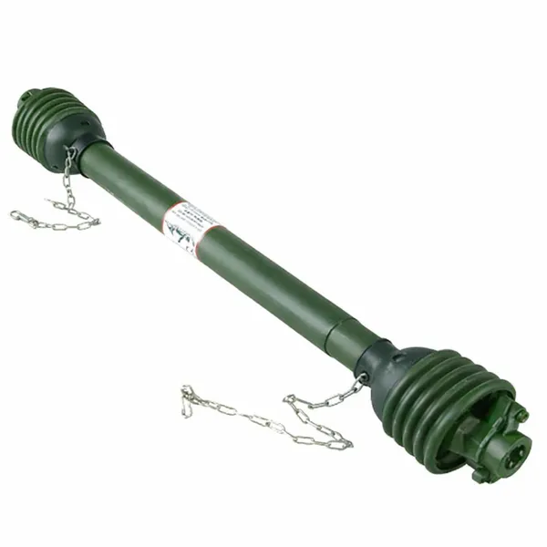
Triangular PTO Shaft for Agricultural Equipment
Agricultural PTO Shaft Australia — Triangular Pto Shaft Manufacturer
The triangular tube profile — three engagement lobes set 120° apart — is the long-running European answer to high-torque, low-cost driveline design. Its symmetric three-point engagement spreads contact stress across a wide arc, which is why triangular PTO shafts dominate older European tractor platforms and remain the standard on many wood-chipper, fertiliser spreader and irrigation pump drivelines.
This triangular PTO shaft is part of our agricultural-driveline catalogue, manufactured in an ISO-9001-certified facility in Hangzhou, China and shipped to farmers, dealers and OEMs across Australia, New Zealand, Europe and the Americas. As a dedicated tractor PTO shaft manufacturer with over 22 years of design, broaching, balancing and assembly experience, we treat the PTO driveline as what it really is — a high-energy power-transfer device that, when correctly engineered, runs invisibly for years; when poorly built, fails catastrophically and damages everything around it.
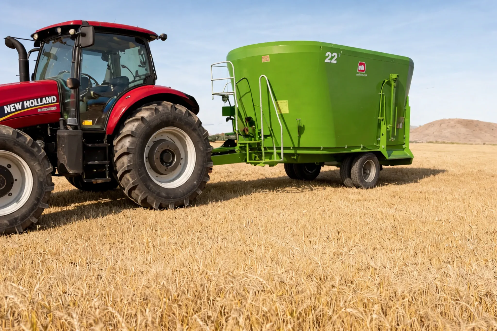
Compatible machinery includes fertiliser spreaders, wood chippers, irrigation pumps, lighter rotary tillers, manure spreaders, slurry tankers, plus any other PTO-driven implement that matches the dimensional, spline and torque envelope of this model. The shaft is supplied complete with a two-piece ISO 5673 plastic guard, safety chain, lubrication nipples and a calibration tag traceable back to its production batch — letting you re-order an identical replacement five years from now without guessing the spec.
Our PTO drive shaft supplier service is built around three commitments: (1) we will not ship a shaft until it has passed dynamic balance to G6.3 or better; (2) every cross & bearing kit is greased with EP-2 lithium and seal-tested before assembly; and (3) every guard system is impact-tested at –20 °C to confirm it will not shatter in a cold-morning start.
Technical Specifications — Tractor PTO Drive Shaft
The table below lists 20 verified parameters for this model. Spec sheets in CAD-compatible PDF and STEP/IGES are available on request.
| Parameter | Value |
|---|---|
| Series | T4 / T6 heavy series |
| Tube Profile | Square |
| Working Length (closed) | 810 mm / 32″ |
| Working Length (extended) | 1300 mm / 51″ |
| Cross & Bearing Type | 35 × 94 mm |
| Yoke Type | Friction lock (FL) |
| Tractor-end Spline | 1 3/8″ 6 spline |
| Tube Material | Q345B low-alloy steel |
| Tube Wall Thickness | 4.0 mm |
| Cross Hardness (HRC) | Core 30–40 HRC |
| Power Rating | 120 HP / 89 kW @ 1000 rpm |
| Torque Rating | 1100 Nm continuous |
| Safety Device | Overrunning clutch (RL) |
| Shielding Type | Heavy-duty triple-cone shield |
| Guard Color | Red (RAL 3020) |
| Guard Material | Reinforced HDPE with anti-static additive |
| 表面处理 | Cataphoretic coating (KTL) |
| Lubrication Interval | Lifetime grease (no-maintenance crosses) |
| Packing | Wooden case for export |
| Yoke Process | Investment casting + CNC |
Customisation Scope — OEM & ODM PTO Shaft Service
Every dimension on this triangular PTO shaft can be customised to your tractor-and-implement geometry. The customisation envelope is wide; the table below summarises the parameters most often modified for our Australian and OEM customers:
| Customisation Parameter | Available Range |
|---|---|
| Working length (closed) | 580 mm to 1,250 mm — cut to within ±2 mm |
| Spline pattern (each end) | 1 1/8″-6, 1 3/8″-6, 1 3/8″-21, 1 3/4″-6, 1 3/4″-20, plus metric DIN/ASAE/JIS and customer-supplied OEM |
| Yoke style | Push pin, bolt pin, double push pin, ball-collar, quick-release, snap-ring, friction-lock |
| Tube profile | Star, lemon, triangular, square, hex, splined round, OEM custom |
| Safety device | Shear-bolt clutch, friction clutch (single/double disc), ratchet, cam, free-wheel, slip-clutch |
| Guard colour | Yellow / orange / black / green / red / RAL or Pantone match |
| Surface finish | Cataphoretic (KTL), powder-coat, zinc-plate, hot-dip galvanise, phosphate + epoxy |
| Logo / branding | Silk-screen on guard, embossed on yoke (≥200 pcs), engraved end caps |
| Packaging | Anti-rust paper + carton / honeycomb double-wall / wooden case / pallet shrink-wrap / OEM box |