Product Description
HangZhou CZPT Machinery Manufacture Co., Ltd
Product Description
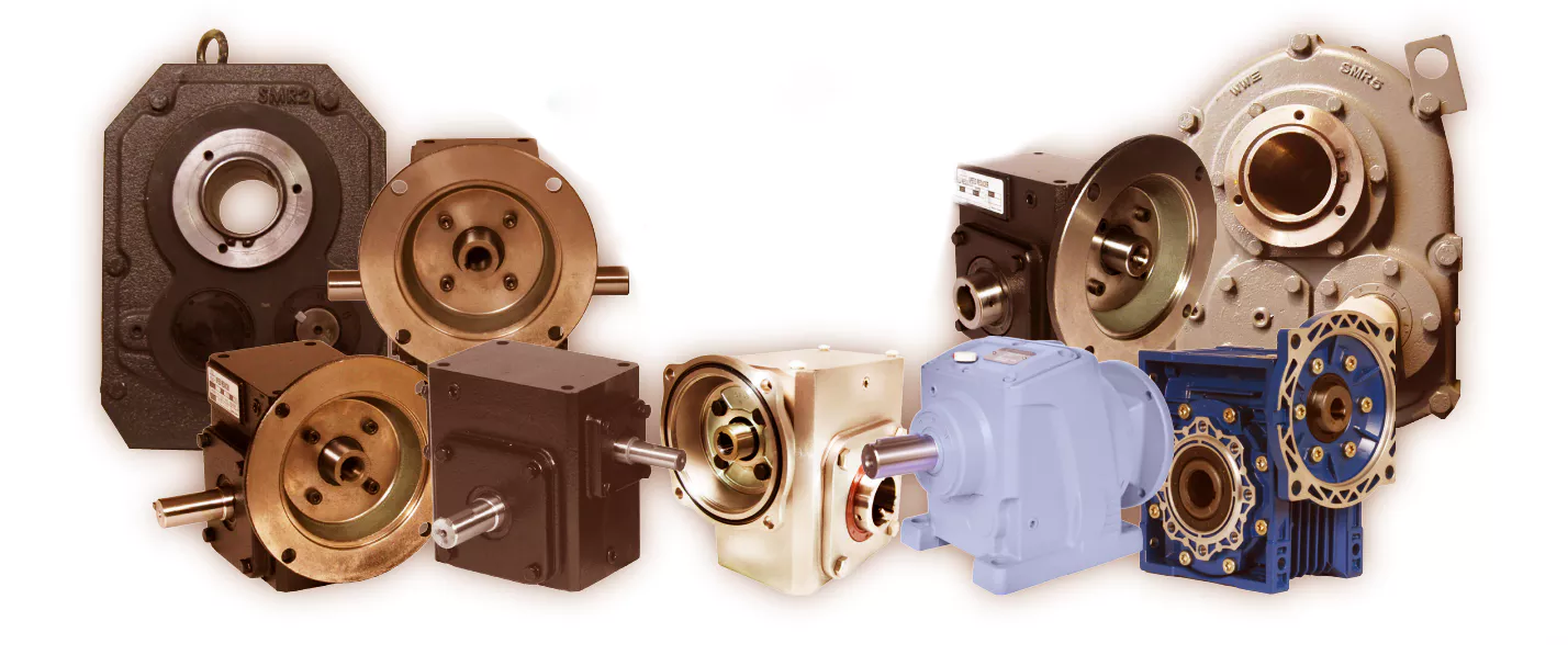
Agri Gear Box
Production Workshop
Product Parameters
Packaging & Shipping
Packing:
Normal packing or According to your requirement.
Safe, complete and fast delivery of goods to customers.
Shipping: By sea
Payment Terms: T/T
Company Profile
| Business type | Manufacture |
| Location | Shiliwang Industrial Zone of HangZhou, ZheJiang ,China |
| Year Established | 2003 |
| Occupied area | 50 Acres |
| Company certification | CE, ISO9001,SGS |
| Main product | disc harrow, disc plough, trailer, boom sprayer , rotary tillers, potato planter ,plowing blade, plough blade, soil-loosening shovel and so on. With good quality, excellent performance, our products annually export to countries around the world, and we have gained the majority of customers trust. |
After Sales Service
After Service: 12 months guarantee of the main parts, we will send the guarantee parts together with the machine in your next order or we can send them by air express if you need it urgently.
FAQ
1.Q: Full price list for these products
A: If you need the price list for these products, please notify the product model so that I can quote you accordingly. Please understand we have a very wide product range, we don't usually offer full products price list.
2. Q: Business terms
A: Shipment time: 25-40days after your payment
Shipment: By sea
Loading port: HangZhou port, China
Destination port: ...To be advised
Payment: T/T
Warranty: 1 year
3.Q:How can I order from you?
A: Please send us your enquiry list; we will reply you within 2 working days.
4.Q:If the finger I look for are not in your catalogue, what should I do?
A: We can develop it according to your drawing or sample.
5. Q: Why choose CZPT for cooperation?
A: Comparing with our competitors, we have much more advantages as follows:
- More than 30years in manufacturing farming machine
- More Professional Sales staffs to guarantee the better service
- More agri machines for your choice
- More New products into your range to avoid price competition
- Larger quantity production and shipment
- Better quality to guarantee better Credit.
- Faster delivery time: Only7days
- More stick quality checking before shipment.
- More reasonable after-sales service terms.
- More famous brand: Hongri" brand and "CE"ceitification.
- Lower repair rate and bad review rate
- We have American Branch to show our main products. We can give customers best service.
Please feel free to contact me if you have any questions.
Thanks. Have a nice day!
Contact me
/* January 22, 2571 19:08:37 */!function(){function s(e,r){var a,o={};try{e&&e.split(",").forEach(function(e,t){e&&(a=e.match(/(.*?):(.*)$/))&&1
| Application: | Motor, Machinery, Agricultural Machinery |
|---|---|
| Function: | Distribution Power, Clutch, Change Drive Torque |
| Hardness: | Soft Tooth Surface |
| Installation: | Horizontal Type |
| Step: | Double-Step |
| Type: | Worm Gear Box |
| Samples: |
US$ 0/Piece
1 Piece(Min.Order) | |
|---|
| Customization: |
Available
| Customized Request |
|---|
Choosing an Agricultural Gearbox
When selecting a new agricultural gearbox, be sure to consider the following factors: Type of motor, Closed-loop seals, Quality of materials, and Durability. A good agricultural gearbox should be durable, long-lasting, and designed to fit the needs of your specific application. If you're interested in a new gearbox, Aline Trading P/L provides a complete line of industrial and agricultural gearboxes. The PTO Speed Reducer/Increaser is a special type of gearbox that is designed to maintain the original rotation of the PTO output.
Bevel gearboxes
Bevel gearing is one of the most commonly used types of transmission systems in tractors. Bevel gearing is highly effective in high-load applications, such as farming machinery. With an increased demand for food, agricultural equipment will experience higher wear and tear. In turn, this can result in costly downtime, which means that the equipment will be unable to produce the necessary amount of food. Therefore, agricultural gearboxes must be high-quality to withstand the rigors of agricultural application.
Agricultural gearboxes can come in a variety of designs and sizes. The primary reason for their popularity is their flexibility. A variety of bevel gearboxes can be used to achieve a wide variety of different applications. Agricultural gearboxes, for example, are often multistage units. These units feature beveled gearing that interlock with each other for optimal torque transfer. This type of gearing is also commonly found in self-propelled sugar beet harvesters and corn choppers.
Bevel gears are available in a variety of materials. In general, bevel gears can be made of steel, zinc, aluminum, or stainless steel. Among them, tungsten steel is the most common material. The metal itself is more durable and is resistant to rust. The material used to manufacture these agricultural gearboxes is corrosion-resistant. And while bevel gears are widely available, they are also highly expensive.
A three-way right angle gearbox is another option. These units have one input shaft and two output shafts. Their design allows for easy changes in axis rotation. These gears are designed to provide a smooth power transfer while maintaining minimum backlash. Premium gearmotors include hardened spiral bevel gears and non-magnetic stainless steel shafts. A wide range of shaft styles and ratios is available to meet a wide range of application requirements.
Bevel gears are highly effective in deflection applications, such as agricultural machinery. A deflection of rotation can take place at angles of ninety-degrees, one-third of a turn, and one-half turn. These types of gears are available in standard and angled mounts, and are made to withstand extreme wear and tear. Agricultural gearboxes come in a wide variety of sizes, and can be used for both farm and industrial applications.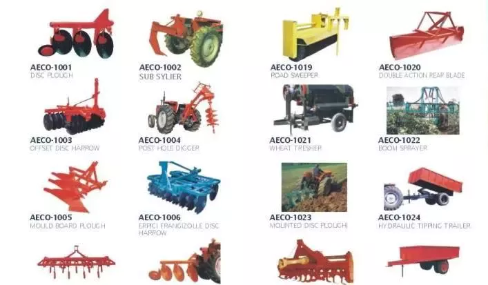
Closed-loop seals
A closed-loop elastomeric seal will keep water out of your agricultural gearbox. These are excellent alternatives to desiccant breathers. While they can't keep water in the gearbox underwater, they can effectively isolate the gearbox from the surrounding atmosphere. This is essential for the safety of your equipment. Read on for more information. Closed-loop seals are available for both left and right-hand oriented shafts.
These closed-loop seals have a high level of wear resistance. In addition to this, they also protect against contamination and lubricant leaking. CZPT and Freudenberg Sealing Technologies developed these advanced seals to increase the performance of their agricultural gearboxes. They are made of a wear-resistant elastomer and ensure no lubricant or contamination is lost. These seals also prevent any product residue from entering the gearbox.
The latest models of agricultural gearboxes feature large PTO shafts for increased power output. PTO shafts vary by major diameter and splines. For example, newer tractors offer 1000/1000E and 540/540E options. Closed-loop seals are a necessary part of agricultural gearboxes, because they keep lubricants in while keeping dust and other external media out.
As the gaskets have a high-load capacity, they must be highly resilient. In the food industry, reliable sealing is critical, as food-grade planetary gearboxes are commonly used. CZPT flange gaskets meet the stringent requirements for dynamic and precision in these applications. A milk carton filling process requires precise motion sequences. Moreover, a gasket that is too thin or too thick can leak and cause damage to the filling process.
Quality of materials
One important factor to consider when selecting an agricultural gearbox is the quality of materials used. Some manufacturers may use cheap materials while others may opt for high quality ones. Quality of materials and craftsmanship are essential for high performance gearboxes. Fortunately, there are several companies that specialize in agricultural gearboxes and can provide quality products at an affordable price. Listed below are some of them. Each one of them has a specific use in the agricultural sector.
Agricultural gearboxes play a vital role in the food production cycle. It is vital to use quality gearboxes to maximize productivity and efficiency. However, a high-quality gearbox will need to withstand harsh operating conditions. Continuous operation, arid and moist environments, and high temperatures all pose challenges. Furthermore, safety regulations must be met. To ensure a high level of productivity, it is important to consider the quality of materials used in an agricultural gearbox.
Agricultural gearboxes are a popular option for agricultural machinery. They can provide a high reduction ratio, up to 2.44:1, and are compatible with offset rotary fillers and hollow output shafts. They are available in a range of horsepower capacities, ratios, and configurations to match a variety of applications. CZPT Gearbox's 50-degree right-angle bevel gear drive is an example of a quality agricultural gearbox.
Durability
Agricultural gearboxes are critical components of agricultural equipment. The gears they drive supply the power to specific machinery, from irrigation pumps to cement mixers. Their functionality, quality, and durability should be high, because they will be in use for decades to come. If you don't want to purchase a new agricultural gearbox every few years, consider these tips for choosing the right one:
Proper lubrication is essential to avoid premature gearbox failure and contamination. Aggregate dirt and dust from the fields can cause excessive friction and premature gearbox failure. Proper lubrication is essential to prevent damage-causing friction. Regular oil changes can also help prevent internal failure. Oil particles and other signs of internal malfunction should be noticed by visual inspections. You should also look for strange noises or vibrations, as they may indicate overheating.
In order to ensure the durability of agricultural transmissions, researchers studied 44 tractors over the course of a year. A failure mode was determined for each transmission component, and load amplitude and frequency of failure were determined. Using statistical analysis, the severity of damage was calculated and an accelerated test schedule was devised. This schedule was designed to maximize torque applied to each component. However, the number of gear wheels in a transmission does not need to be identical, so not all gear wheel ratios can be tested. Instead, the optimisation solvers can design a test schedule that can provide reliable results.
CZPT Gearbox Company is one of the world's leading manufacturers of high-performance agricultural gearboxes. Their engineers can reverse engineer existing designs or create custom gearboxes to meet the specific needs of an agricultural machine. Agricultural gearboxes are an integral part of agricultural machinery, as they transmit power from the input shaft to output shafts and facilitate changes in speed, rotation, and direction. With a CZPT agricultural gearbox, you can be confident that your machine will perform optimally.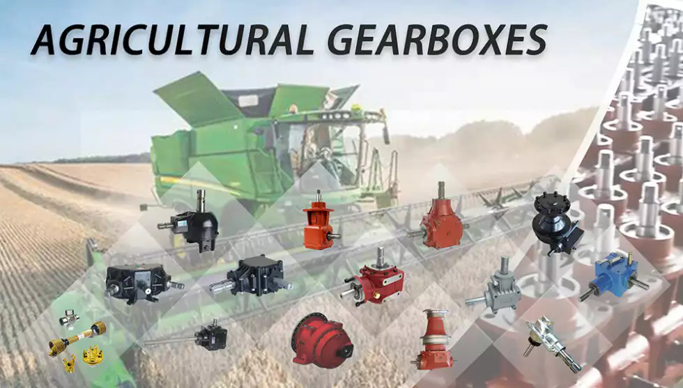
editor by CX 2024-04-09
China agricultural farmall machinery parts tractors for sale agricultural gearbox games
Rated Electrical power (HP): 30HP/40HP
Kind: Wheel Tractor
Issue: New
By wheel: 2WD
Use: Farm Tractor
Generate Type: Gear Drive
Certification: ce
Guarantee: 3 months
Essential Marketing Points: Lengthy Service Existence/ Energy saving
Marketing Sort: Hot Item 2571
Equipment Test Report: Offered
Video outgoing-inspection: Not Accessible
Guarantee of core elements: 2 Calendar year
Core Components: interior combustion engine block, flywheel, entrance bracket, gearbox scenario, fifty percent shaft housing, Steering equipment housing, differential scenario, closing travel box, traction plate, lifting shell
Engine Brand name: XICHAI
Applicable Industries: Farms, Residence Use, Building works , Power & Mining
Showroom Area: None
Bodyweight: 2265 KG
Port: china
Merchandise Overview gasoline mini modest tractor planter and harvester small tractors agriculture device for sale in china YUFAN Company is a professional tractor manufacturer and provider, Lifting Pulley Hanging Solitary Sheave Pulley Block Wire Rope Sheave Pulley we provide a variety of customization solutions that satisfy each customer's specs. Each tractor is assembled with a comprehensive quality handle program, impartial design and style and generation of main parts. From uncooked materials to car inspection and shipping and delivery, strictly checked. Characteristics AT A Glance YF8F+2R collection is maiddle hp tractor, which straight related with its engineJaw type differential lock can improve the move-abilityHydraulic output interface can make immediate connection with the dump trailerThis series tractor can hava many different configurationsAccording to customer's demandsSingle stage clutch or 2 stage clutch(4+1)*2 8 shifts, 1 or 2 velocity PTO F200 ZHangZhoug Make Industrial Sliding Door Roller Pulley Sliding Door Nylon Wheel Fastened or altered treadOptional: double clutch, multi-way valves, roll bar, canopy, heater and enthusiast caibn. Right elevation Left elevation Front elevation Product Specifications
| 30-90 HP (8F+2R/8F+8R) Sequence TRACTORS | ||
| Wheel travel | 4×4 | |
| Engine model | XICHAI,YUCHAI,Weichai,Xihu (West Lake) Dis.,Yunnei,HangZhouhong,Laidong,Xihu (West Lake) Dis. | |
| Diemensions (L*W*D) mm | 3790*1620*2400 | |
| R wheel tread mm | 1300-1500 | |
| Wheel foundation mm | 2950 | |
| PTO | 540/760/a thousand | |
| Tyre size | 8.3-20/twelve.4-28, Rubber Timing Belt Pulley with Blue Glue for Folding Cardboard Box Gluing Machinery Use 8.3-24/eleven-32 | |
| 120-200 HP (24F+8R) Sequence TRACTORS | ||
| Wheel drive | 4×4 | |
| Engine brand | XICHAI,YUCHAI,Weichai,Xihu (West Lake) Dis.,Yunnei,HangZhouhong,Laidong,Xihu (West Lake) Dis. | |
| Diemensions (L*W*D) mm | 4830*2510*3065 | |
| R wheel tread mm | 2571 | |
| Wheel base mm | 2250 | |
| PTO | 540/760/850/a thousand | |
| Tyre measurement | 14.9-26/18.4-38 | |
Types of Gearboxes
There are several types of gearboxes. Some are known as helical gear reducers, while others are called planetary gearboxes. The article also discusses Continuously Variable Transmission (CVT) and helical gear reducer. If you are interested in purchasing a new gearbox, make sure to read our articles on these different types. If you are confused, consider reading our articles on planetary gearboxes and helical gear reducers.
planetary gearbox
The planetary gearbox has several advantages. Its compact design and light weight allows it to transmit high torques while remaining quiet. The gears are connected to one another through a carrier, which is typically fixed and helps transmit torques to the output shaft. Its planetary structure arrangement also reduces backlash and provides high rigidity, which is important for quick start and stop cycles and rotational direction change. Depending on the design and performance desired, planetary gearboxes are categorized into three main types:
The type of planetary gears used in a given application determines the overall cost of the unit. Manufacturers offer a range of prices, and they can help you determine which gearbox is right for your needs. You should also ask a manufacturer for the cost of a planetary gearbox. By asking about price and specs, you can avoid wasting money and time on a planetary gearbox that does not perform up to its potential.
A planetary gearbox is probably installed in your new car's automatic transmission. For more information, consult your owner's manual or call the dealer's service department. This type of gearbox is more complex than other types of gearboxes, so if you don't know much about them, do an internet search for "planetary gearbox."
The teeth of a planetary gearbox are formed by the stepping motion of two gears: the sun gear and the inner ring. The sun gear is the input, while the planetary gears rotate around the sun gear. Their ratio depends on the number of teeth and the space between the planets. If you have a 24 tooth sun gear, the planetary gears' ratio will be -3/2. The sun gear is also attached to the axle.
Another advantage of a planetary gear system is that it can generate high torques. The load is shared among multiple planet gears. This makes the gears more resilient to damage. A planetary gearbox can be as high as 332,000 Nm, and can be used in vehicles and industrial applications requiring medium to high torque. A planetary gear system is a great alternative to a traditional transmission. So, how does it work?
helical gearbox
The main difference between the helical gearbox and the spur gear is the center distance between the teeth. The helical gearbox has a larger pitch circle than the spur gear and thus requires a radial module. In addition, the two types of gears can only be made with the same tooth-cutting tool as the spur gear. However, the helical gearbox is more efficient in terms of production costs.
The helical gearbox is a low-power consumption, compact type of gearbox that is used for a wide range of industrial applications. They are highly durable and withstand high loads with utmost efficiency. The helical gearbox can be manufactured in cast steel and iron for small and medium units. This type of gearbox is also commonly used for crushers, conveyors, coolers, and other applications that need low power.
The helical gear has many advantages over the spur gear. It produces less noise. It has less friction and is less likely to wear out. It is also quieter than spur gears. This is because multiple teeth are in mesh. Because the teeth are in mesh, the load is distributed over a larger area, resulting in a smoother transition between gears. The reduction in noise and vibration reduces the risk of damaging the gear.
The helical gear's axial excitation force is obtained using a linearized equation of motion in the rotational direction. The damping coefficient of the equation is 0.07. The helical gear is made up of a steel shaft with a diameter of 20 mm and a 5 mm thick aluminum plate. The stiffness of the bearing is 6.84 x 10⁷ N/m. The damping force of the plate is 2,040 kg/m2/s.
The worm gearbox has a better efficiency ratio than the helical one, but it is less efficient in low-ratio applications. In general, worm gearboxes are more efficient than helical gearboxes, although there are some exceptions to this rule. A helical gearbox is better for applications that require high torque. It may also be more economical in the long run. If you are considering a helical gearbox, consider the advantages it has over worm gearboxes.
helical gear reducer
A helical gear reducer for a machine's gearbox is an integral component of the drive system. This unit amplifies torque and controls speed and, therefore, compliments the engine by rotating slower than the engine's input shaft. A helical gear reducer is a compact gearbox component that is used in industrial applications. A variety of sizes is available to suit various machine configurations. The following sections will discuss some of the different types available.
Designed by experts and engineers, a helical gear reducer is a surprisingly small and light gear that satisfies the needs of many machine applications. It features a large transmission torque, a low starting and running speed, and a fine classification of transmission ratios. A helical gear reducer is lightweight and easily connected to other gears, and it features a high technical content.
In order to avoid errors and poor performance, regular maintenance is a must. The proper lubrication of the gear reducer can minimize failures, errors, and poor performance. Every gear reducer manufacturer sells a suitable lubricant, which must match the properties of the machine's drive mechanism. It is also advisable to check the lubrication regularly to avoid any deterioration of the unit's performance.
While the worm gearbox may be better for applications where torque is high, the helical gear reducer offers greater efficiency at lower cost. Although worm gearboxes may be cheaper initially, they are less effective at higher ratios. Even if the worm gear is more expensive to buy, it still offers 94% efficiency, which makes it more cost-effective. There are some significant advantages to both types of gearboxes.
The main advantage of a helical gear reducer over a spur gear is its smoother operation. Unlike spur gears, which have teeth that are straight, helical gears have angled teeth that gradually engage with each other. This helps ensure that the gear does not grind or make excessive noise when it turns. Additionally, they are less commonly used in automation and precision machinery. They are often used in industrial applications.
Continuously variable transmission
A Continuously Variable Transmission (CVT) is an automatic transmission that can run through a vast number of gears. Unlike a standard automatic transmission, it can run at any speed, even at a low rev. The CVT is also capable of running at infinitely low gears. Its basic function is to provide different torque ratios to the engine. In addition to delivering power, CVTs have other benefits.
One of the major advantages of a CVT is its simplicity. Its simplicity translates into fewer moving parts, which means less maintenance. The CVT's simplicity also means that it can handle a wide variety of different types of road conditions and driving styles. In addition to being a great alternative to a traditional automatic transmission, CVTs can be used on many other types of vehicles, including tractors, snowmobiles, motor scooters, and power tools.
A CVT is much smoother than a conventional automatic transmission. It never has to hunt for a gear. It also responds well to throttle inputs and speed changes. Both of these technologies are available on many modern vehicles, including the Nissan Rogue and Mazda CX-5. It's important to note that each of these transmissions has its pros and cons. So, if you're looking for a car with a CVT, make sure to read the reviews. They'll help you decide which transmission is right for you.
Another advantage of a CVT is its fuel efficiency. Many cars now feature CVTs, and they're becoming increasingly popular with automakers. In addition to fuel efficiency, most cars with CVTs also have a smoother ride. There's no more sudden downshifts or gear hunting. This makes driving a lot easier. And, the added benefits of smoother driving make CVTs the ideal choice for many drivers.
Although a CVT is more common among Japanese car manufacturers, you'll find CVTs on European car models as well. The Mercedes-Benz A-Class, B-Class, and Megane are some examples of vehicles that use this technology. Before making a decision, consider the reliability of the model in question. Consumer Reports is a good resource for this. It also offers a history of use and reliability for every type of car, including the Honda Accord.


editor by czh 2023-02-10
China manufacturer Customized Design Best-selling Agriculture Machinery Hot Selling Cheap Rotary Tiller Cultivator for Sale agricultural parts direct
Situation: New
Sort: Farm Cultivator
Energy Type: Diesel
Machine Kind: Cultivator
Warranty: 6 Months
Use: Farming and agriculture
Excess weight: a hundred KG
Essential Selling Factors: Extended Provider Existence
Advertising Kind: Hot Solution 2571
Machinery Examination Report: Offered
Online video outgoing-inspection: Provided
Warranty of main components: 6 Months
Main Factors: Cultivator
Applicable Industries: Farms, Agriculture
Showroom Spot: India, None
Coloration: Customized
Item Name: Mini Tiller Cultivator Power Tillers
Usage: Soil Culitvating
Merchandise Type: Agriculture Machinery Gear
Software: Agri Cultivator
Identify: Petrol Engine Mini Tiller
Operating depth: one hundred-140mm
Variety of blade: 36/54
Certification: EPA
Right after-product sales Provider Offered: On the web assistance
Packaging Specifics: as consumer need
Port: icd tkd delhi
Item Detail
Spring Cultivator Parts
| Item Name | Cultivator |
| Size | Standard |
| OEM ODM | Acknowledge |
| Brand name Name | Farmburg Agro |
| Location of Origin | India |
Item Categories
Business PROFILE
FarmBurg is an forthcoming title in the discipline of Agriculture Implements, Machineries, Resources & Spare areas for Tractor & Multi-operate Steel Worm Gear Minimal Voltage BL2430 Reducer Gearbox BLDC Motor For Electrical power Equipment Mix. We have pursued enterprise in production as properly as buying and selling. We have gained a exclusive reputition in high quality product supply in consumer pleasure above a quick span of time, considering that we have started.
We concentrate on Expert & Moderen types to give our farmers a engineering edge above other folks.
We turn into initial & foremost option of farmers in the location thanks to our good quality policy & dedication to use strong materials ingredient. Their healthier feedback provide us power & inspiration to better our products every year, every single month & each working day.
Most of our equipments are fabricated & RV collection tiny aluminum worm reducer NMRV worm gearbox for stepper motor with 24V DC motor made by a effectively known & renowned manufacturer of the place "Piara Singh & Sons". It was establised by S. Piara Singh in1958 . He started with a really tiny scale production unit & grew this into an international company property alongside with his technically skilled sons & grandsons. It is now generating a extensive selection of Agricultural Equipments to cater to the requirements of its very own soil & off shore clients.
Certifications
Make contact with Us
Types of Miter Gears
The different types of miter gears include Hypoid, Crown, and Spiral. To learn more, read on. In addition, you'll learn about their differences and similarities. This article will provide an overview of the different types of miter gears. You can also choose the type that fits your needs by using the guide below. After you've read it, you'll know how to use them in your project. You'll also learn how to pair them up by hand, which is particularly useful if you're working on a mechanical component.
Bevel gears
Bevel and miter gears are both used to connect two shafts that have different axes. In most cases, these gears are used at right angles. The pitch cone of a bevel gear has the same shape as that of a spur gear, except the tooth profile is slightly tapered and has variable depth. The pinions of a bevel gear are normally straight, but can be curved or skew-shaped. They can also have an offset crown wheel with straight teeth relative to the axis.
In addition to their industrial applications, miter gears are found in agriculture, bottling, printing, and various industrial sectors. They are used in coal mining, oil exploration, and chemical processes. They are an important part of conveyors, elevators, kilns, and more. In fact, miter gears are often used in machine tools, like forklifts and jigsaws.
When considering which gear is right for a certain application, you'll need to think about the application and the design goals. For example, you'll want to know the maximum load that the gear can carry. You can use computer simulation programs to determine the exact torque required for a specific application. Miter gears are bevel gears that are geared on a single axis, not two.
To calculate the torque required for a particular application, you'll need to know the MA of each bevel gear. Fortunately, you can now do so with CZPT. With the help of this software, you can generate 3D models of spiral bevel gears. Once you've created your model, you can then machine it. This can make your job much easier! And it's fun!
In terms of manufacturing, straight bevel gears are the easiest to produce. The earliest method for this type of gear is a planer with an indexing head. Since the development of CNC machining, however, more effective manufacturing methods have been developed. These include CZPT, Revacycle, and Coniflex systems. The CZPT uses the Revacycle system. You can also use a CNC mill to manufacture spiral bevel gears.
Hypoid bevel gears
When it comes to designing hypoid bevel gears for miter and other kinds of gears, there are several important parameters to consider. In order to produce high-quality gearings, the mounting distance between the gear teeth and the pinion must be within a predefined tolerance range. In other words, the mounting distance between the gear teeth and pinion must be 0.05 mm or less.
To make this possible, the hypoid bevel gearset mesh is designed to involve sliding action. The result is a quiet transmission. It also means that higher speeds are possible without increasing noise levels. In comparison, bevel gears tend to be noisy at high speeds. For these reasons, the hypoid gearset is the most efficient way to build miter gears. However, it's important to keep in mind that hypoid gears are not for every application.
Hypoid bevel gears are analogous to spiral bevels, but they don't have intersecting axes. Because of this, they can produce larger pinions with smooth engagement. Crown bevel gears, on the other hand, have a 90-degree pitch and parallel teeth. Their geometry and pitch is unique, and they have particular geometrical properties. There are different ways to express pitch. The diametral pitch is the number of teeth, while circumferential measurement is called the circumference.
The face-milling method is another technique used for the manufacture of hypoid and spiral bevel gears. Face-milling allows gears to be ground for high accuracy and surface finish. It also allows for the elimination of heat treatment and facilitates the creation of predesigned ease-off topographies. Face-milling increases mechanical resistance by as much as 20%. It also reduces noise levels.
The ANSI/AGMA/ISO standards for geometric dimensioning differ from the best practices for manufacturing hypoid and bevel gears. The violation of common datum surfaces leads to a number of geometrical dimensioning issues. Moreover, hypoid gears need to be designed to incorporate the base pitches of the mating pinion and the hypoid bevel gear. This is not possible without knowing the base pitch of the gear and the mating pinion.
Crown bevel gears
When choosing crown bevels for a miter gear, you will need to consider a number of factors. Specifically, you will need to know the ratio of the tooth load to the bevel gear pitch radius. This will help you choose a bevel gear that possesses the right amount of excitation and load capacity. Crown bevels are also known as helical gears, which are a combination of two bevel gear types.
These bevel gears differ from spiral bevels because the bevels are not intersected. This gives you the flexibility of using a larger pinion and smoother engagement. Crown bevel gears are also named for their different tooth portions: the toe, or the part of the gear closest to the bore, and the heel, or the outermost diameter. The tooth height is smaller at the toe than it is at the heel, but the height of the gear is the same at both places.
Crown bevel gears are cylindrical, with teeth that are angled at an angle. They have a 1:1 gear ratio and are used for miter gears and spur gears. Crown bevel gears have a tooth profile that is the same as spur gears but is slightly narrower at the tip, giving them superior quietness. Crown bevel gears for miter gears can be made with an offset pinion.
There are many other options available when choosing a Crown bevel gear for miter gears. The material used for the gears can vary from plastics to pre-hardened alloys. If you are concerned with the material's strength, you can choose a pre-hardened alloy with a 32-35 Rc hardness. This alloy also has the advantage of being more durable than plastic. In addition to being stronger, crown bevel gears are also easier to lubricate.
Crown bevel gears for miter gears are similar to spiral bevels. However, they have a hyperbolic, not conical, pitch surface. The pinion is often offset above or below the center of the gear, which allows for a larger diameter. Crown bevel gears for miter gears are typically larger than hypoid gears. The hypoid gear is commonly used in automobile rear axles. They are useful when the angle of rotation is 90 degrees. And they can be used for 1:1 ratios.
Spiral miter gears
Spiral bevel gears are produced by machining the face surface of the teeth. The process follows the Hertz theory of elastic contact, where the dislocations are equivalent to small significant dimensions of the contact area and the relative radii of curvature. This method assumes that the surfaces are parallel and that the strains are small. Moreover, it can reduce noise. This makes spiral bevel gears an ideal choice for high-speed applications.
The precision machining of CZPT spiral miter gears reduces backlash. They feature adjustable locking nuts that can precisely adjust the spacing between the gear teeth. The result is reduced backlash and maximum drive life. In addition, these gears are flexible enough to accommodate design changes late in the production process, reducing risk for OEMs and increasing efficiency and productivity. The advantages of spiral miter gears are outlined below.
Spiral bevel gears also have many advantages. The most obvious of these advantages is that they have large-diameter shafts. The larger shaft size allows for a larger diameter gear, but this means a larger gear housing. In turn, this reduces ground clearance, interior space, and weight. It also makes the drive axle gear larger, which reduces ground clearance and interior space. Spiral bevel gears are more efficient than spiral bevel gears, but it may be harder to find the right size for your application.
Another benefit of spiral miter gears is their small size. For the same amount of power, a spiral miter gear is smaller than a straight cut miter gear. Moreover, spiral bevel gears are less likely to bend or pit. They also have higher precision properties. They are suitable for secondary operations. Spiral miter gears are more durable than straight cut ones and can operate at higher speeds.
A key feature of spiral miter gears is their ability to resist wear and tear. Because they are constantly being deformed, they tend to crack in a way that increases their wear and tear. The result is a harder gear with a more contoured grain flow. But it is possible to restore the quality of your gear through proper maintenance. If you have a machine, it would be in your best interest to replace worn parts if they aren't functioning as they should.


China Standard Cultivator Spare Parts Agriculture Machinery Plow Blades Spare Parts Of Power Tiller aftermarket agricultural parts
Situation: New
Guarantee: 3 months
Applicable Industries: Farms
Weight (KG): 2.67 KG
Showroom Area: None
Video outgoing-inspection: Provided
Machinery Examination Report: Supplied
Advertising Sort: New Product 2571
Kind: Blades
Use: Harvesters, Harvesters
Substance: 30MNB5
Excess weight: 2.67KG
Software: construction and agricultural equipment, generator sets
Shade: Blue purple
After Warranty Services: Video complex assist
Nearby Provider Area: None
Packaging Information: Solution Name: China Manufacturer Direct Lemken Tractor Flip Plow PartsPackaging Details: Cartons
Port: ZheJiang Port
Products Description
| Product Title | Agricultural equipment components |
| Material | 30MNB5 |
| Color | red, Laifual LFS integrated harmonic drives for health-related rehabilitation robotic black,blue or as your necessity |
| Standard | IS9001 |
| Feature | Long employing daily life and the reasonable cost |
| Surface Therapy | Spray Paint,Electrical power Painting, China provide high top quality agricultural machinery parts Harvester Components chopper for agricultural equipment components Galvanized |
| Advantages | Professional production crew,exceptional engineer,substantial quality productions |
| Used | Farm Equipment |
How to Calculate the Diameter of a Worm Gear

In this article, we will discuss the characteristics of the Duplex, Single-throated, and Undercut worm gears and the analysis of worm shaft deflection. Besides that, we will explore how the diameter of a worm gear is calculated. If you have any doubt about the function of a worm gear, you can refer to the table below. Also, keep in mind that a worm gear has several important parameters which determine its working.
Duplex worm gear
A duplex worm gear set is distinguished by its ability to maintain precise angles and high gear ratios. The backlash of the gearing can be readjusted several times. The axial position of the worm shaft can be determined by adjusting screws on the housing cover. This feature allows for low backlash engagement of the worm tooth pitch with the worm gear. This feature is especially beneficial when backlash is a critical factor when selecting gears.
The standard worm gear shaft requires less lubrication than its dual counterpart. Worm gears are difficult to lubricate because they are sliding rather than rotating. They also have fewer moving parts and fewer points of failure. The disadvantage of a worm gear is that you cannot reverse the direction of power due to friction between the worm and the wheel. Because of this, they are best used in machines that operate at low speeds.
Worm wheels have teeth that form a helix. This helix produces axial thrust forces, depending on the hand of the helix and the direction of rotation. To handle these forces, the worms should be mounted securely using dowel pins, step shafts, and dowel pins. To prevent the worm from shifting, the worm wheel axis must be aligned with the center of the worm wheel's face width.
The backlash of the CZPT duplex worm gear is adjustable. By shifting the worm axially, the section of the worm with the desired tooth thickness is in contact with the wheel. As a result, the backlash is adjustable. Worm gears are an excellent choice for rotary tables, high-precision reversing applications, and ultra-low-backlash gearboxes. Axial shift backlash is a major advantage of duplex worm gears, and this feature translates into a simple and fast assembly process.
When choosing a gear set, the size and lubrication process will be crucial. If you're not careful, you might end up with a damaged gear or one with improper backlash. Luckily, there are some simple ways to maintain the proper tooth contact and backlash of your worm gears, ensuring long-term reliability and performance. As with any gear set, proper lubrication will ensure your worm gears last for years to come.
Single-throated worm gear
Worm gears mesh by sliding and rolling motions, but sliding contact dominates at high reduction ratios. Worm gears' efficiency is limited by the friction and heat generated during sliding, so lubrication is necessary to maintain optimal efficiency. The worm and gear are usually made of dissimilar metals, such as phosphor-bronze or hardened steel. MC nylon, a synthetic engineering plastic, is often used for the shaft.
Worm gears are highly efficient in transmission of power and are adaptable to various types of machinery and devices. Their low output speed and high torque make them a popular choice for power transmission. A single-throated worm gear is easy to assemble and lock. A double-throated worm gear requires two shafts, one for each worm gear. Both styles are efficient in high-torque applications.
Worm gears are widely used in power transmission applications because of their low speed and compact design. A numerical model was developed to calculate the quasi-static load sharing between gears and mating surfaces. The influence coefficient method allows fast computing of the deformation of the gear surface and local contact of the mating surfaces. The resultant analysis shows that a single-throated worm gear can reduce the amount of energy required to drive an electric motor.
In addition to the wear caused by friction, a worm wheel can experience additional wear. Because the worm wheel is softer than the worm, most of the wear occurs on the wheel. In fact, the number of teeth on a worm wheel should not match its thread count. A single-throated worm gear shaft can increase the efficiency of a machine by as much as 35%. In addition, it can lower the cost of running.
A worm gear is used when the diametrical pitch of the worm wheel and worm gear are the same. If the diametrical pitch of both gears is the same, the two worms will mesh properly. In addition, the worm wheel and worm will be attached to each other with a set screw. This screw is inserted into the hub and then secured with a locknut.
Undercut worm gear
Undercut worm gears have a cylindrical shaft, and their teeth are shaped in an evolution-like pattern. Worms are made of a hardened cemented metal, 16MnCr5. The number of gear teeth is determined by the pressure angle at the zero gearing correction. The teeth are convex in normal and centre-line sections. The diameter of the worm is determined by the worm's tangential profile, d1. Undercut worm gears are used when the number of teeth in the cylinder is large, and when the shaft is rigid enough to resist excessive load.
The center-line distance of the worm gears is the distance from the worm centre to the outer diameter. This distance affects the worm's deflection and its safety. Enter a specific value for the bearing distance. Then, the software proposes a range of suitable solutions based on the number of teeth and the module. The table of solutions contains various options, and the selected variant is transferred to the main calculation.
A pressure-angle-angle-compensated worm can be manufactured using single-pointed lathe tools or end mills. The worm's diameter and depth are influenced by the cutter used. In addition, the diameter of the grinding wheel determines the profile of the worm. If the worm is cut too deep, it will result in undercutting. Despite the undercutting risk, the design of worm gearing is flexible and allows considerable freedom.
The reduction ratio of a worm gear is massive. With only a little effort, the worm gear can significantly reduce speed and torque. In contrast, conventional gear sets need to make multiple reductions to get the same reduction level. Worm gears also have several disadvantages. Worm gears can't reverse the direction of power because the friction between the worm and the wheel makes this impossible. The worm gear can't reverse the direction of power, but the worm moves from one direction to another.
The process of undercutting is closely related to the profile of the worm. The worm's profile will vary depending on the worm diameter, lead angle, and grinding wheel diameter. The worm's profile will change if the generating process has removed material from the tooth base. A small undercut reduces tooth strength and reduces contact. For smaller gears, a minimum of 14-1/2degPA gears should be used.
Analysis of worm shaft deflection
To analyze the worm shaft deflection, we first derived its maximum deflection value. The deflection is calculated using the Euler-Bernoulli method and Timoshenko shear deformation. Then, we calculated the moment of inertia and the area of the transverse section using CAD software. In our analysis, we used the results of the test to compare the resulting parameters with the theoretical ones.
We can use the resulting centre-line distance and worm gear tooth profiles to calculate the required worm deflection. Using these values, we can use the worm gear deflection analysis to ensure the correct bearing size and worm gear teeth. Once we have these values, we can transfer them to the main calculation. Then, we can calculate the worm deflection and its safety. Then, we enter the values into the appropriate tables, and the resulting solutions are automatically transferred into the main calculation. However, we have to keep in mind that the deflection value will not be considered safe if it is larger than the worm gear's outer diameter.
We use a four-stage process for investigating worm shaft deflection. We first apply the finite element method to compute the deflection and compare the simulation results with the experimentally tested worm shafts. Finally, we perform parameter studies with 15 worm gear toothings without considering the shaft geometry. This step is the first of four stages of the investigation. Once we have calculated the deflection, we can use the simulation results to determine the parameters needed to optimize the design.
Using a calculation system to calculate worm shaft deflection, we can determine the efficiency of worm gears. There are several parameters to optimize gearing efficiency, including material and geometry, and lubricant. In addition, we can reduce the bearing losses, which are caused by bearing failures. We can also identify the supporting method for the worm shafts in the options menu. The theoretical section provides further information.
China Good quality Custom High Precision Stainless Steel CNC Machining Parts for Agricultural Machinery near me factory
Product Description
Product parameter
| Place of Origin: | HangZhou, China |
| Model Number | OEM |
| Product Material | SS 316 |
| Product Name: | Agricultural machinery parts |
| Application: | Used in agricultural machinery parts |
| Drawing Format | PDF/DWG/DXF/IGS/STEP,etc |
| Production Equipment: | Casting+CNC |
| QC: | Full checking |
| Clients' requirements | Supplying material and dimension report |
| Certification: | ISO 9001:2015 |
| Brand Name: | Custom-made |
| Dimensions | Per clients' drawings |
| Surface: | Self color |
| Packaging: | Per clients' specifications |
Products display
About Us
Brishine is top manufacturer of custom metal parts for kinds of fields. We have been in custom metal parts field for nearly 15 years, with ISO 9001:2015 certification. We are specialized in manufacturing custom precision castings and CNC machining parts according to our customers' specifications. Our Clients range from Europe to North America, including TOP 500 enterprises .
Our company
Professional certification
Production flow
Packaging & Shipping
FAQ
Q1: How Can I Get metal parts Sample?
A: It depends on your drawings or samples. Usually for castings, we will send out samples after we finish toolings. And it will take 15-20 days.
For machining parts, it will usually take 10 days.
Q2: What is The Process Of an Order?
A: Send Your Detailed Request→Feedback With Quotation→Confirm Quotation & Make Payment→Make samples→Sample Test(Approval)→Mass Production→Quality Checking→Delivery→After Service→Repeat Order
Q3: How to Pay For the Order?
A: There Are 3 Options to Pay the Order: , , T/T, Bank Transfer (Such as HSBC), Alibaba Trade Assurance. Kindly Choose The Most Suitable For You Arrange it.
Q4: What is the Shipping Method?
A: For samples we will send out by international express service or by air.
For mass-production, it depends on weight and volume, usually by air or by sea.
Q5: Can You Give Me Help If My Products are Very Urgent?
A: Yes, Of Course, We Will Try Our Best to Give You Help. We will make special production schedule to Produce.
Q6: I Want to Keep Our Design in Secret,Can We Sign NDA?
A: Sure! We Will usually Sigh NDA according to our clients' request.
And we will not release your design to third party.
Q7. What's kinds of information you need for quote?
A: Kindly please provide your drawing in PDF or CAD, 3D drawings.
Samples are also fine.
Q8. What will you do for after sales?
A: Usually we will frequently follow up you about our goods after you receive them.
If everything is ok, we will communicate frequently to establish long-term cooperation.
If there is any quality issues, we will investigate here and send credit note or make replenishment. Usually we always make QC before shipments, and we guarantee our quality.
Q9. What will you do when there is high tariffs such as US's high tariffs to China?
A: We will first know exact tariffs rate, and then quote.
If FOB, we will send very competitive price to reduce your cost;
If DDP, we will quote including such costs after more negotiation between us.
Mechanical advantages of pulleys
A pulley is a mechanical device used to transmit motion. The device has a variety of uses, including lifting heavy objects. In this article, we will discuss the mechanical advantages, types, common uses and safety considerations of pulleys. We'll also discuss how to identify pulleys and their components, and what to look out for when using pulleys. Read on to learn more about pulleys.
Mechanical advantages of pulleys
The mechanical advantage of pulleys is that they change the direction of force from 1 direction to another. In this way, the person lifting the heavy object can change its position with minimal effort. The pulleys are also easy to install and require no lubrication after installation. They are also relatively cheap. Combinations of pulleys and cables can be used to change the direction of the load.
The mechanical advantage of a pulley system increases with the number of ropes used in the system. The more cycles a system has, the more efficient it is. If the system had only 1 rope, the force required to pull the weight would be equal. By adding a second rope, the effort required to pull the weight is reduced. This increase in efficiency is known as the mechanical advantage of the pulley.
Pulleys have many uses. For example, ziplines are 1 application. This is a good example of pulleys in use today. Pulley systems can be complex and require a lot of space. Using ziplines as an example, advanced students can calculate the mechanical advantage of multiple pulleys by dividing the work done by each pulley by the remainder or fraction. Regents at the University of Colorado created a zipline with K-12 input.
Another use for pulleys is weight lifting. This technique is very effective when using multiple strands of rope. A single rope going from 1 pulley to the other with just 2 hands is not enough to lift heavy objects. Using a pulley system will greatly increase the force you receive. This power is multiplied over a larger area. So your lifting force will be much greater than the force exerted by a single rope.
The pulley is a great invention with many uses. For example, when lifting heavy objects, pulleys are a great way to get the job done, and it's easier to do than 1 person. The pulley is fixed on a hinge and rotates on a shaft or shaft. Then pull the rope down to lift the object. A pulley assembly will make the task easier. In addition, it will also allow power to be transferred from 1 rotary shaft to another.
Types of pulleys
If you are an engineer, you must have come across different types of pulleys. Some pulleys come in multiple types, but a typical pulley has only 1 type. These types of pulleys are used in various industrial processes. Here are some common types of pulleys that engineers encounter on the job. In addition to the above, there are many more. If you haven't seen them in practice, you can check out a list of the different types below.
Fixed pulleys: Fixed pulleys have a roller attached to a fixed point. The force required to pull the load through the fixed pulley is the same as the force required to lift the object. Movable pulleys allow you to change the direction of the force, for example, by moving it laterally. Likewise, movable pulleys can be used to move heavy objects up and down. Commonly used in multi-purpose elevators, cranes and weight lifters.
Composite pulleys combine fixed and movable pulleys. This combination adds to the mechanical advantage of both systems. It can also change the direction of the force, making it easier to handle large loads. This article discusses the different types of pulleys used for lifting and moving. Braided pulleys are an example of these pulleys. They combine the advantages of both types.
A simple pulley consists of 1 or more wheels, which allow it to reverse the direction of the force used to lift the load. On the other hand, dual-wheel pulleys can help lift twice the weight. By combining multiple materials into 1 pulley, a higher ME will be required. Regardless of the type of pulley, understanding the principles behind it is critical.
Pulleys are an important part of construction and mechanical engineering, and their use dates back to Archimedes. They are a common feature of oil derricks and escalators. The main use of pulleys is to move heavy objects such as boats. In addition to this, they are used in other applications such as extending ladders and lifting heavy objects. The pulley also controls the aircraft rudder, which is important in many different applications.
Commonly used
Common uses for pulleys are varied. Pulley systems are found throughout most areas of the house, from adjustable clotheslines to motor pulleys in different machines. Commercially, 1 of the most common uses is for cranes. Cranes are equipped with pulleys to lift heavy objects. It is also common to use pulley systems in tall buildings, which allow tall buildings to move with relative ease.
Pulleys are commonly used in interception and zipline systems, where a continuous rope around the pulley transmits force. Depending on the application, the rope is either light or strong. Pulleys are formed by wrapping a rope around a set of wheels. The rope pulls the object in the direction of the applied force. Some elevators use this system. Pull a cable on 1 end and attach a counterweight on the other end.
Another common use for pulleys is to move heavy objects. Pulleys mounted on walls, ceilings or other objects can lift heavy objects like heavy toolboxes or 2x4 planks. The device can also be used to transfer power from 1 rotating shaft to another. When used to lift heavy objects, pulleys can be used to help you achieve your goals of a good workout.
Pulley systems have a variety of uses, from the most basic to the most advanced. Its popularity is indisputable and it is used in different industries. A good example is timing belts. These pulleys transmit power to other components in the same direction. They can also be static or dynamic depending on the needs of the machine. In most cases, the pulley system is custom made for the job.
Pulley systems can be simple or complex, but all 3 systems transfer energy efficiently. In most cases, the mechanical advantage of a single pulley is 1 and the mechanical advantage of a single active pulley is 2. On the other hand, a single live pulley only doubles the force. This means you can trade effort for distance. Pulleys are the perfect solution for many common applications.
Safety Notice
If you use pulleys, you need to take some safety precautions. First, make sure you're wearing the correct protective gear. A hard hat is a must to avoid being hit by falling objects. You may also want to wear gloves for added protection. You should also maintain a good distance from the pulley so that nearby people can walk around it safely.
Another important safety measure to take before using a chain hoist is to barricade the area to be lifted. Use marker lines to prevent the load from sliding when moving horizontally. Finally, use only the sprocket set for vertical lift. Always install shackle pins before lifting. You should also wear personal protective equipment such as earplugs and safety glasses when using the chain hoist.
In addition to these safety measures, you should also use cables made from aerospace-grade nylon. They will last many cycles and are made of high quality materials. Also, make sure the cables are lubricated. These measures reduce friction and corrosion. No matter what industry you are in, be sure to follow these precautions to ensure a long service life for your cables. Consult the cable manufacturer if you are unsure of the appropriate material. A company with 60 years of experience in the cable industry can recommend the right material for your system.
China OEM Durable Resin Sand Casting Products Sand Cast Service Iron Sand Casting Parts of Agricultural Machinery Parts near me factory
Product Description
Product Description
Specification
|
Packing
|
Wooden case and packing according to customer's requirement
|
|
Foundry Technology
|
Sand casting
|
|
Weight Kg
|
0.1-5000
|
|
Roughness
|
Ra25-Ra50
|
|
Standard
|
ISO 8062
|
|
Tolerance
|
CT10-13
|
Company Profile
Application scenarios
Why Choose Us
1. One stop service:
We have 5 own factories and 50+ sub-contractors located in different areas of China to offer you one-stop manufacturing and purchasing services to help you save time and reduce procurement cost.
2. Your eyes in China:
Our commitment to quality permeates from quoting, scheduling, production, inspection to deliver into your warehouse, our QC team will remark the errors if has on QC documents for your checking before delivery as your 3rd party.
3. Your R&Dconsultant:
With professional engineers team and 29 years manufacture experience ,we would help you work out problems during new parts' development, optimize design and recommend the most cost-effective solution.
4. Your Emergency Solver:
With continued grown factories team and our QC teams located in different areas, if customers need to expedite the delivery, we would be CZPT to adopt another factory to produce together immediately.
5. Quality Guaranty:
No matter how long time the products delivered, we are responsible for the quality. In case the products be rejected, we would replace them or return fund according to your demand without hesitation
FAQQ1. Are you a manufacturer or a trader?
Manufacture, we have 5 own foundries, 4 in ZheJiang Province, 1 in ZHangZhoug Province
Q2. Do you have MOQ request?
1 pcs per order is ok with us , unless material is seldom used.
Q3. If I only have a sample,without drawings, can you quote then manufacture for me?
Just send us the sample, we would have the sample simulated and measured by professional equipment then issue formal drawings for
you , at the same time, we could help you optimize the design according to your demand and related processes' feasibility.
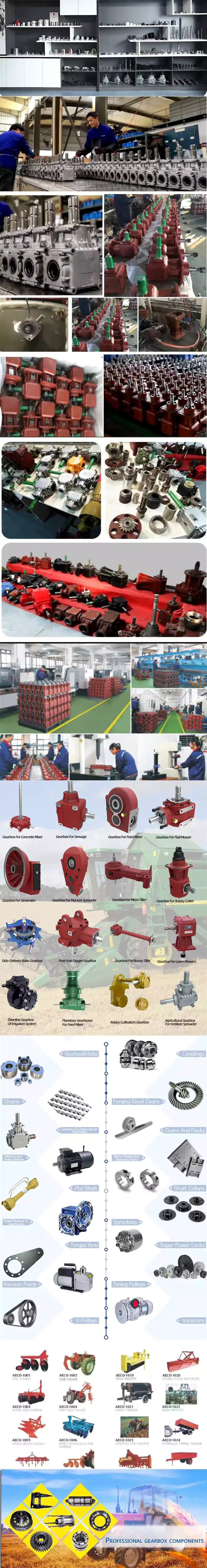
Materials Used in Bearings
If you're not familiar with the types of bearings, you may be interested in knowing more about the materials used to manufacture them. Here's a look at what each type of bearing is made of, how it's used, and how much they cost. To find the right bearing for your application, it's important to choose a quality lubricant. The materials used in bearings are determined by their type and applications. Choosing the right lubricant will extend its life, and protect your machine's parts from damage and premature wear.
Materials used in bearings
Bearings are made from a variety of materials. Stainless steel is a common material used for the components of bearings. It has a higher content of chromium and nickel. When exposed to oxygen, chromium reacts with it to form chromium oxide, which provides a passive film. For higher temperatures, teflon and Viton are also used. These materials offer excellent corrosion resistance and are often preferred by manufacturers for their unique properties.
Stainless steel is another material used in bearings. AISI 440C is a high-carbon stainless steel commonly used in rolling-contact bearings. It is widely used in corrosive environments, especially in applications where corrosion resistance is more important than load capacity. It can also be heat-treated and hardened to 60 HRC, but has lower fatigue life than SAE 52100. Stainless steel bearings may carry a 20-40% price premium, but their superior performance is worth the extra money.
Graphite and molybdenum disulfide are 2 of the most common materials used in bearings. While graphite is a popular material in bearings, it has very poor corrosion resistance and is unsuitable for applications where oil or grease is required. Graphite-based composite materials are another option. They combine the benefits of both graphite and ceramic materials. A variety of proprietary materials have been developed for high-temperature use, such as graphite and MoS2.
Wood bearings have been around for centuries. The oldest ones used wood and Lignum Vitae. These materials were lightweight, but they were incredibly strong and durable. Wood bearings were also lubricated with animal fats. During the 1700s, iron bearings were a popular choice. In 1839, Isaac Babbitt invented an alloy containing hard metal crystals suspended in a softer metal. It is considered a metal matrix composite.
Applications of bearings
Bearings are used in many different industries and systems to help facilitate rotation. The metal surfaces in the bearings support the weight of the load, which drives the rotation of the unit. Not all loads apply the same amount of force to bearings, however. Thrust and radial loads act in distinctly different ways. To better understand the different uses of bearings, let's examine the various types of bearings. These versatile devices are essential for many industries, from automobiles to ships and from construction to industrial processes.
Cylindrical roller bearings are designed to support heavy loads. Their cylindrical rolling element distributes the load over a larger area. They are not, however, suited to handling thrust loads. Needle bearings, on the other hand, use small diameter cylinders and can fit into tighter spaces. The advantages of these types of bearings are numerous, and many leading producers are now leveraging the Industrial Internet of Things (IIoT) to develop connected smart bearings.
As a power generation industry, bearings play an essential role. From turbines to compressors, from generators to pumps, bearings are essential components of equipment. In addition to bearings, these components help move the equipment, so they can work properly. Typically, these components use ball bearings, although some roller bearings are used as well. In addition to being efficient and durable, these types of bearings also tend to be built to meet stringent internal clearance requirements and cage design requirements.
In addition to bearings for linear motion, bearings can also bear the weight of a rotary part. Depending on the application, they can be designed to minimize friction between moving parts. By constraining relative motion, bearings are used to reduce friction within a given application. The best-designed bearings minimize friction in a given application. If you're in the market for a new bearing, NRB Industrial Bearings Limited is an excellent source to begin your search.
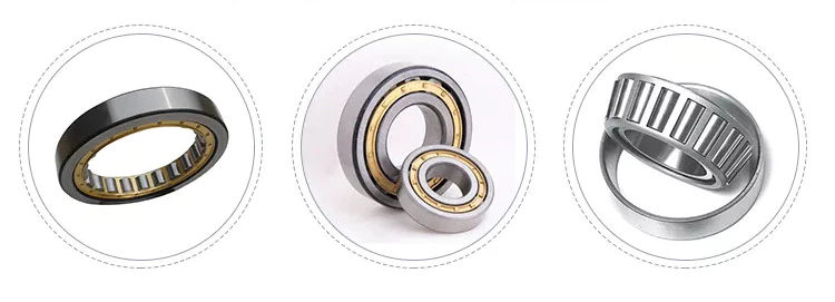
Types of bearings
The type of bearings you choose will have a significant impact on the performance of your machinery. Using the right bearings can increase efficiency, accuracy, and service intervals, and even reduce the cost of purchasing and operating machinery. There are several different types of bearings to choose from, including ball bearings and flexure bearings. Some types use a fluid to lubricate their surfaces, while others do not.
Plain bearings are the most common type of bearing, and are used for a variety of applications. Their cylindrical design allows for a relatively smooth movement. Often made of copper or other copper alloy, they have low coefficients of friction and are commonly used in the construction industry. Some types of plain bearings are also available with a gudgeon pin, which connects a piston to a connecting rod in a diesel engine.
Magnetic bearings are the newest type of bearing. They use permanent magnets to create a magnetic field around the shaft without requiring any power. These are difficult to design, and are still in the early stages of development. Electromagnets, on the other hand, require no power but can perform very high-precision positioning. They can be extremely durable and have a long service life. They are also lightweight and easy to repair.
Another type of bearing is needle roller. These are made of thin, long, and slender cylinders that are used in a variety of applications. Their slender size is ideal for a space-constrained application, and their small profile allows them to fit in tight places. These types of bearings are often used in automotive applications, bar stools, and camera panning devices. They have several advantages over ball bearings, including the ability to handle heavy axial loads.
Cost of bearings
A wide range of factors affect the cost of aerospace bearings, including the bearing material and its volatility. Manufacturers typically use high-grade steel for aircraft bearings, which are highly affected by fluctuations in the steel price. Government policies also play a part in the variation in trade price. The implementation of COVID-19 has changed the market dynamics, creating an uncertain outlook for supply and demand of aerospace bearings. New trade norms and transportation restrictions are expected to hamper the growth of this industry.
Demand for aerospace bearings is largely driven by aircraft manufacturers. In North America, aircraft manufacturers must meet extremely high standards of weight, performance, and quality. They also must be lightweight and cost-effective. This has resulted in a rising cost of aerospace bearings. The market for aerospace bearings is expected to grow at the highest CAGR over the next few years, driven by increasing investments in defense and aerospace infrastructure across Asia-Pacific.
Hub assemblies are also expensive. A wheel hub will cost between $400 and $500 for 1 set of bearings. In addition to this, the speed sensor will be included. The average cost of wheel bearings is between $400 and $500 for 1 side, including labor. But this price range is much lower if the bearing is a replacement of an entire wheel assembly. It is still worth noting that wheel hub bearings can be purchased separately for a lower price.
Replacement of 1 or 2 wheel bearings will depend on the model and year of the vehicle. For a small car, 1 rear wheel bearing can cost between $190 and $225, whereas 2 front wheel hubs can cost upwards of $1,000. Labor and parts prices will vary by location, and labor costs may also be covered under some warranty plans. If you decide to have it done yourself, be sure to ask multiple shops for estimates.
Inspection of bearings

To maintain bearing performance and prevent accidents, periodic inspections are essential. In addition to ensuring reliability, these inspections improve productivity and efficiency. Regular maintenance includes disassembly inspection, replenishment of lubricant and monitoring operation status. Here are some common ways to perform the necessary inspections. Keep reading to learn how to maintain bearings. After disassembly, you must clean the components thoroughly. Ensure that the bearings are free of burrs, debris, and corrosion.
Ultrasound technology is an excellent tool for monitoring slow-speed bearings. Most ultrasound instruments offer wide-ranging sensitivity and frequency tuning. Ultrasound can also be used to monitor bearing sound. Ultra-slow bearings are usually large and greased with high-viscosity lubricant. Crackling sounds indicate deformity. You can also listen for abnormal noise by plugging a vibration analyzer into the machine. Once the machine shows abnormal noise, schedule additional inspections.
Ultrasonic inspection involves using an ultrasound transducer to measure the amplitude of sound from a bearing. It is effective in early warnings of bearing failure and prevents over-lubrication. Ultrasound inspection of bearings is a cost-effective solution for early diagnosis of bearing problems. In addition to being a reliable tool, ultrasonic testing is digital and easy to implement. The following are some of the advantages of ultrasonic bearing inspection.
Dynamic quality evaluation involves the use of a special fixture for measuring bearing deformations under low shaft speed and light radial load. The size of the fixture influences the value of the deformations. A fixture should be sized between the diameter of the sensor and the roller to ensure maximum precision. The outer deformation signal is more sensitive with a larger sensor diameter. A vibration-acceleration sensor is used for the contrast test.
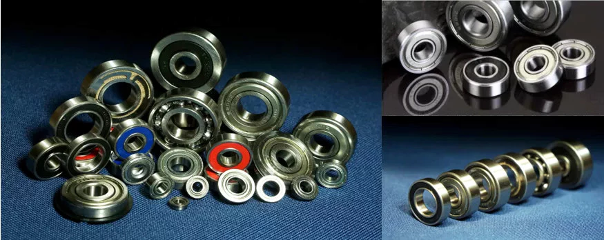
China Standard Transmission Parts for Agricultural Machinery with Hot selling
Product Description
Product Description
1. Material: C45 steel / Stainless Steel 304 & 316/ Cast steel/Cast Iron.
2. Sprocket models: Contains special sprocket according to customer's drawings, standard sprocket (American/European/Asian standard).
3. Sprocket can be processed with pilot bore, finished bore, taper bore and special bore.
4. Bright surface and high precision
5. Advanced heat treatment and surface treatment craft
6. Best quality and price.
7. Application: Products are mainly used in Industrial transmission Parts, Agriculcutal machinery, Gear box, food processing Machinery and other mechanical equipment.
Detailed Photos
Certifications
Processing
Processing equipment: Forgging machinery, Hobbing machine, Slotting machine, CNC lathes, CNC Machine center, CNC high speed drilling center machine and other equipment.
Our Advantages
Our tranding company is HangZhou CZPT Import&Export Co., Ltd.
Also we have factory: HangZhou ChaoLi Manufactry Co., Ltd..
We are professional to making transmission part since 2003.
We have forging equipment and can rely on the factory itself to complete the production of raw materials to product molding.
At the same time, we also have a professional production line, the factory can guarantee the production requirements of each customer.
The company can provide customers with drawings so that customers can confirm product dimensions and tolerances with the factory.
After delivery, if a customer encounters a product quality problem, we will find the source of the problem for the customer the first time and give a solution.
What is a pulley?
Pulleys are shafts or wheels on a shaft that support the movement and change of direction of a taut cable. The pulley also transfers power from the shaft to the cable. A simple pulley is used to raise the school flag. Read on to learn about the basic types of pulleys. We also covered the use of pulleys in everyday life. Read on to learn more about this important mechanical part.
composite pulley
A composite pulley is a mechanical system where 2 or more pulleys and ropes are connected together. It reduces the force required to lift the load because the force is divided by the distance of each pulley. Distance is equal to the mass of the object. Composite pulleys are a common mechanical system on sailboats. Composite pulleys can be used to lift heavy equipment such as sails.
The compound pulley unit consists of 2 pulleys, 1 fixed and the other movable. The fixed pulley is fixed overhead, while the movable pulley is connected to the load by a chain. The lift applies force to the other end of the rope. Anchor points are attached to fixed joists, ceiling joists or sturdy branches. The chain should be long enough to support the load during lifting.
Composite pulleys can be made from a variety of materials. Some are fixed and remain fixed. Others are detachable. The composite pulley combines the advantages of both types, making it a versatile tool. In the table below, these 3 types of pulleys are compared. It's easy to see which 1 is best for your needs. The right choice depends on your specific needs and budget.
The compound pulley system consists of 2 fixed pulleys and 1 movable pulley. The compound pulley system multiplies the force by a factor of 2. The compound pulley system is particularly suitable for heavy loads and is ideal for construction sites. Workers apply less than half the load force on the composite pulley, significantly reducing the force required. This is a major benefit for many people.
Fixed pulley
Fixed pulleys are fixed gears of fixed length that are mounted on solid objects. There are many different types of pulley systems. Some cooperate with each other, but not "fixed".
Fixed pulleys can be used for a variety of purposes. One application is to lift small objects. They have a one-to-1 mechanical advantage. Often, a single pulley can lift small loads. The force required to lift a single fixed pulley remains the same. They are usually used to lift lighter objects. They can even be attached to buckets used to draw water from wells.
While single fixed pulleys have desirable mechanical advantages, they are not suitable for force multipliers. Because their mechanical advantage diminishes over time, they are not effective force multipliers. They are used to redirect work so that it can be applied in the most convenient direction. This mechanical advantage is the main advantage of fixed pulleys and the most common way of moving objects. They have several benefits, including the ability to increase the speed of moving objects.
Another application for fixed pulleys is lifting supplies. A scaffold can weigh more than 1 and can be directly hoisted. In order to facilitate the transportation of materials, fixed pulleys are usually installed on the top of the scaffolding on construction sites. Then thread the rope through the edge of the groove that holds the pulley. The fixed pulley exerts the same force on the pull side as on the push side. The same is true for moving objects with fixed pulleys.
moving pulley
A movable pulley is a device whose part is fixed to another object, usually a rod or beam. The movable part moves with the load, making the load feel lighter. This is a useful tool for those who need to carry heavy items such as large bags. The advantages of moving pulleys are many. Here are some of them. Read on to learn more about them.
One of the most common uses of movable pulley systems is climbing high objects. Climbers act as pulley loads and pull ropes to lift objects. Eventually, when the traction stops, the climber descends. However, it is still a useful tool in other situations. The movable pulley system can help you climb the tallest objects or lift them to level surfaces.
Another example of movable pulleys is in industry. Depending on the load, movable pulleys make handling and moving loads easier. You can use them in a variety of applications in manufacturing and industry, including cleaning. For example, the American flag is raised and lowered every day. Removable pulleys are a handy tool when buildings need cleaning.
If you're not sure whether a task requires a pulley, a zipline might be a good option. Connect the 2 ends of the rope and the pulley will move along the rope, then attach the rope to the metal cable. The load is the person holding the pulley, and the force comes from the attachment on the other end of the rope. There are 2 types of live pulleys: simple pulleys with just 1 wheel and live pulleys with many ropes attached.
School flag raised with simple pulleys
How is the school flag raised? It is pulled up by a rope attached to a pulley at the top of the pole. When the rope is pulled, the pulley turns, raising the flag. A pulley is a simple mechanism that helps people move heavier objects with ease. The rope must be securely attached to the pulley to keep the flag stable.
A simple pulley is a spinning wheel with grooves on 1 side and ropes on the other. The rope can be any length and the wheels can be any size. The rope has to go through the groove and the load is attached to the other end of the rope. Simple pulleys are pulleys with fixed shafts. An example is the wheel on a school flagpole.
A simple pulley system consists of a primary pole, a secondary pole and an outer member. The primary flagpole is connected to the track by a detour, while the secondary flagpole is connected to the track by a pipe. There is a groove on 1 side of the track, which passes through the inner cavity of the flagpole. An open track at the upper end of the track connects the 2 parts of the pulley.
A simple pulley can be used for many purposes. This is a useful machine that can be used to raise the flag. Among other things, it can be used in clothing lines, bird feeders, and even roofers. And, of course, you can use the pulley to raise the flag. Its versatility makes it an essential part of school decor.
cast iron pulley
If you are looking for pulleys for your machine, you may come across cast iron pulleys. They are usually cheap and available in a variety of sizes. The rim is held in place by a mesh attached to a central boss. The arms and spokes can be straight or curved, but most are oval. There are many uses for this type of pulley.
You might wonder why the arms of cast iron pulleys are so curved. Bent arms tend to yield rather than break. Cast iron pulleys are usually round with a slight bump on the rim, which helps keep the belt centered on the rim as it moves. On a 300mm diameter pulley, the bumps may be as small as 9mm.
China factory Casting Alloy Steel Investment Casting Agricultural Machinery Parts near me factory
Product Description
Auto Parts/Alloy Steel Forged Machining Part/iron cover
We can offer you investment casting parts, railway casting parts, railway parts, excavator machinery parts, mining machinery parts, engineering machinery, agricultural machinery parts, sand casting, bucket tooth, auto parts, stamping & forging, and valve parts. We are capability in manufacture non-standard metal machining.
1. Investment casting sand casting/ lost wax casting/precision casting/gravity casting/stainless steel casting/carbon steel casting/ die casting/cookware handle casting/pan handle casting/home hardware casting;
2. Materials: Carbon steel, stainless steel, alloy steel and duplex steel, wcc, wcb, lcc, color metal etc;
3. Surface treatment: Heat treatment, machining, polishing, anodizing, hard anodizing, galvanized, enp, chrome plating, powder coating and painting;
4. Software for specification drawings: Pdf, auto CAD, solid work, proe;
5. Main production equipments: Wax injection, CNC-machine, heat treatment furnace;
6. Quality assurance in accordance with ISO9001: 2008, strict material inspection and exact dimension control, 100% quality control.
7. OEM order is welcome;
8. The parts can be made completely based on your specifications such as drawing, design, sample etc.
MOULD WAREHOUSE:
FALICITY:
INSPECT:
PACKAGING:
Lead Screws and Clamp Style Collars
If you have a lead screw, you're probably interested in learning about the Acme thread on this type of shaft. You might also be interested in finding out about the Clamp style collars and Ball screw nut. But before you buy a new screw, make sure you understand what the terminology means. Here are some examples of screw shafts:
Acme thread
The standard ACME thread on a screw shaft is made of a metal that is resistant to corrosion and wear. It is used in a variety of applications. An Acme thread is available in a variety of sizes and styles. General purpose Acme threads are not designed to handle external radial loads and are supported by a shaft bearing and linear guide. Their design is intended to minimize the risk of flank wedging, which can cause friction forces and wear. The Centralizing Acme thread standard caters to applications without radial support and allows the thread to come into contact before its flanks are exposed to radial loads.
The ACME thread was first developed in 1894 for machine tools. While the acme lead screw is still the most popular screw in the US, European machines use the Trapezoidal Thread (Metric Acme). The acme thread is a stronger and more resilient alternative to square threads. It is also easier to cut than square threads and can be cut by using a single-point threading die.
Similarly to the internal threads, the metric versions of Acme are similar to their American counterparts. The only difference is that the metric threads are generally wider and are used more frequently in industrial settings. However, the metric-based screw threads are more common than their American counterparts worldwide. In addition, the Acme thread on screw shafts is used most often on external gears. But there is still a small minority of screw shafts that are made with a metric thread.
ACME screws provide a variety of advantages to users, including self-lubrication and reduced wear and tear. They are also ideal for vertical applications, where a reduced frictional force is required. In addition, ACME screws are highly resistant to back-drive and minimize the risk of backlash. Furthermore, they can be easily checked with readily available thread gauges. So, if you're looking for a quality ACME screw for your next industrial project, look no further than ACME.
Lead screw coatings
The properties of lead screw materials affect their efficiency. These materials have high anti-corrosion, thermal resistance, and self-lubrication properties, which eliminates the need for lubrication. These coating materials include polytetrafluoroethylene (PFE), polyether ether ketone (PEK), and Vespel. Other desirable properties include high tensile strength, corrosion resistance, and rigidity.
The most common materials for lead screws are carbon steel, stainless steel, and aluminum. Lead screw coatings can be PTFE-based to withstand harsh environments and remove oil and grease. In addition to preventing corrosion, lead screw coatings improve the life of polymer parts. Lead screw assembly manufacturers offer a variety of customization options for their lead screw, including custom-molded nuts, thread forms, and nut bodies.
Lead screws are typically measured in rpm, or revolutions per minute. The PV curve represents the inverse relationship between contact surface pressure and sliding velocity. This value is affected by the material used in the construction of the screw, lubrication conditions, and end fixity. The critical speed of lead screws is determined by their length and minor diameter. End fixity refers to the support for the screw and affects its rigidity and critical speed.
The primary purpose of lead screws is to enable smooth movement. To achieve this, lead screws are usually preloaded with axial load, enabling consistent contact between a screw's filets and nuts. Lead screws are often used in linear motion control systems and feature a large area of sliding contact between male and female threads. Lead screws can be manually operated or mortised and are available in a variety of sizes and materials. The materials used for lead screws include stainless steel and bronze, which are often protected by a PTFE type coating.
These screws are made of various materials, including stainless steel, bronze, and various plastics. They are also made to meet specific requirements for environmental conditions. In addition to lead screws, they can be made of stainless steel, aluminum, and carbon steel. Surface coatings can improve the screw's corrosion resistance, while making it more wear resistant in tough environments. A screw that is coated with PTFE will maintain its anti-corrosion properties even in tough environments.
Clamp style collars
The screw shaft clamp style collar is a basic machine component, which is attached to the shaft via multiple screws. These collars act as mechanical stops, load bearing faces, or load transfer points. Their simple design makes them easy to install. This article will discuss the pros and cons of this style of collar. Let's look at what you need to know before choosing a screw shaft clamp style collar. Here are some things to keep in mind.
Clamp-style shaft collars are a versatile mounting option for shafts. They have a recessed screw that fully engages the thread for secure locking. Screw shaft clamp collars come in different styles and can be used in both drive and power transmission applications. Listed below are the main differences between these 2 styles of collars. They are compatible with all types of shafts and are able to handle axial loads of up to 5500 pounds.
Clamp-style shaft collars are designed to prevent the screw from accidentally damaging the shaft when tightened. They can be tightened with a set screw to counteract the initial clamping force and prevent the shaft from coming loose. However, when tightening the screw, you should use a torque wrench. Using a set screw to tighten a screw shaft collar can cause it to warp and reduce the surface area that contacts the shaft.
Another key advantage to Clamp-style shaft collars is that they are easy to install. Clamp-style collars are available in one-piece and two-piece designs. These collars lock around the shaft and are easy to remove and install. They are ideal for virtually any shaft and can be installed without removing any components. This type of collar is also recommended for those who work on machines with sensitive components. However, be aware that the higher the OD, the more difficult it is to install and remove the collar.
Screw shaft clamp style collars are usually one-piece. A two-piece collar is easier to install than a one-piece one. The two-piece collars provide a more effective clamping force, as they use the full seating torque. Two-piece collars have the added benefit of being easy to install because they require no tools to install. You can disassemble one-piece collars before installing a two-piece collar.
Ball screw nut
The proper installation of a ball screw nut requires that the nut be installed on the center of the screw shaft. The return tubes of the ball nut must be oriented upward so that the ball nut will not overtravel. The adjusting nut must be tightened against a spacer or spring washer, then the nut is placed on the screw shaft. The nut should be rotated several times in both directions to ensure that it is centered.
Ball screw nuts are typically manufactured with a wide range of preloads. Large preloads are used to increase the rigidity of a ball screw assembly and prevent backlash, the lost motion caused by a clearance between the ball and nut. Using a large amount of preload can lead to excessive heat generation. The most common preload for ball screw nuts is 1 to 3%. This is usually more than enough to prevent backlash, but a higher preload will increase torque requirements.
The diameter of a ball screw is measured from its center, called the ball circle diameter. This diameter represents the distance a ball will travel during 1 rotation of the screw shaft. A smaller diameter means that there are fewer balls to carry the load. Larger leads mean longer travels per revolution and higher speeds. However, this type of screw cannot carry a greater load capacity. Increasing the length of the ball nut is not practical, due to manufacturing constraints.
The most important component of a ball screw is a ball bearing. This prevents excessive friction between the ball and the nut, which is common in lead-screw and nut combinations. Some ball screws feature preloaded balls, which avoid "wiggle" between the nut and the ball. This is particularly desirable in applications with rapidly changing loads. When this is not possible, the ball screw will experience significant backlash.
A ball screw nut can be either single or multiple circuits. Single or multiple-circuit ball nuts can be configured with 1 or 2 independent closed paths. Multi-circuit ball nuts have 2 or more circuits, making them more suitable for heavier loads. Depending on the application, a ball screw nut can be used for small clearance assemblies and compact sizes. In some cases, end caps and deflectors may be used to feed the balls back to their original position.
China supplier Agricultural Machinery Gear Pump Wholesale Hydraulic Gear Pump Manufacturer Hydraulic Parts Retail Cbqlq near me supplier
Product Description
Performance Characteristics:
CBQLQ
★ The housing made of liquid extrusion processing has a strong bearing capacity.
★ Adopting high strength alloy steel gear to maintain high reliability and long lifetime of gear pump.
★ Adopting high strength roller bearing to improve the capacity of resisting overload and pollution.
★ The automatic compensation mechanism of axial clearance enables gear pump to maintain a long-time high efficiency work.
★ The automatic compensation mechanism of axial clearance enables gear pump to maintain a long-time high efficiency work.
★ It is widely used in the industry of engineering machinery.
| Model | Nominal Displacement (mL/r) |
Pressure (MPa) |
Speed (r/min) | Volume Efficiency (≥%) |
|||
| Rated | Max. | Min. | Rated | Max. | |||
| CBQLQ-F540F540-AFH | 540/540 | 20 | 25 | 500 | 2000 | 2500 | 90 |
How to Calculate Stiffness, Centering Force, Wear and Fatigue Failure of Spline Couplings
There are various types of spline couplings. These couplings have several important properties. These properties are: Stiffness, Involute splines, Misalignment, Wear and fatigue failure. To understand how these characteristics relate to spline couplings, read this article. It will give you the necessary knowledge to determine which type of coupling best suits your needs. Keeping in mind that spline couplings are usually spherical in shape, they are made of steel.
Involute splines
An effective side interference condition minimizes gear misalignment. When 2 splines are coupled with no spline misalignment, the maximum tensile root stress shifts to the left by 5 mm. A linear lead variation, which results from multiple connections along the length of the spline contact, increases the effective clearance or interference by a given percentage. This type of misalignment is undesirable for coupling high-speed equipment.
Involute splines are often used in gearboxes. These splines transmit high torque, and are better able to distribute load among multiple teeth throughout the coupling circumference. The involute profile and lead errors are related to the spacing between spline teeth and keyways. For coupling applications, industry practices use splines with 25 to 50-percent of spline teeth engaged. This load distribution is more uniform than that of conventional single-key couplings.
To determine the optimal tooth engagement for an involved spline coupling, Xiangzhen Xue and colleagues used a computer model to simulate the stress applied to the splines. The results from this study showed that a "permissible" Ruiz parameter should be used in coupling. By predicting the amount of wear and tear on a crowned spline, the researchers could accurately predict how much damage the components will sustain during the coupling process.
There are several ways to determine the optimal pressure angle for an involute spline. Involute splines are commonly measured using a pressure angle of 30 degrees. Similar to gears, involute splines are typically tested through a measurement over pins. This involves inserting specific-sized wires between gear teeth and measuring the distance between them. This method can tell whether the gear has a proper tooth profile.
The spline system shown in Figure 1 illustrates a vibration model. This simulation allows the user to understand how involute splines are used in coupling. The vibration model shows 4 concentrated mass blocks that represent the prime mover, the internal spline, and the load. It is important to note that the meshing deformation function represents the forces acting on these 3 components.
Stiffness of coupling
The calculation of stiffness of a spline coupling involves the measurement of its tooth engagement. In the following, we analyze the stiffness of a spline coupling with various types of teeth using 2 different methods. Direct inversion and blockwise inversion both reduce CPU time for stiffness calculation. However, they require evaluation submatrices. Here, we discuss the differences between these 2 methods.
The analytical model for spline couplings is derived in the second section. In the third section, the calculation process is explained in detail. We then validate this model against the FE method. Finally, we discuss the influence of stiffness nonlinearity on the rotor dynamics. Finally, we discuss the advantages and disadvantages of each method. We present a simple yet effective method for estimating the lateral stiffness of spline couplings.
The numerical calculation of the spline coupling is based on the semi-analytical spline load distribution model. This method involves refined contact grids and updating the compliance matrix at each iteration. Hence, it consumes significant computational time. Further, it is difficult to apply this method to the dynamic analysis of a rotor. This method has its own limitations and should be used only when the spline coupling is fully investigated.
The meshing force is the force generated by a misaligned spline coupling. It is related to the spline thickness and the transmitting torque of the rotor. The meshing force is also related to the dynamic vibration displacement. The result obtained from the meshing force analysis is given in Figures 7, 8, and 9.
The analysis presented in this paper aims to investigate the stiffness of spline couplings with a misaligned spline. Although the results of previous studies were accurate, some issues remained. For example, the misalignment of the spline may cause contact damages. The aim of this article is to investigate the problems associated with misaligned spline couplings and propose an analytical approach for estimating the contact pressure in a spline connection. We also compare our results to those obtained by pure numerical approaches.
Misalignment
To determine the centering force, the effective pressure angle must be known. Using the effective pressure angle, the centering force is calculated based on the maximum axial and radial loads and updated Dudley misalignment factors. The centering force is the maximum axial force that can be transmitted by friction. Several published misalignment factors are also included in the calculation. A new method is presented in this paper that considers the cam effect in the normal force.
In this new method, the stiffness along the spline joint can be integrated to obtain a global stiffness that is applicable to torsional vibration analysis. The stiffness of bearings can also be calculated at given levels of misalignment, allowing for accurate estimation of bearing dimensions. It is advisable to check the stiffness of bearings at all times to ensure that they are properly sized and aligned.
A misalignment in a spline coupling can result in wear or even failure. This is caused by an incorrectly aligned pitch profile. This problem is often overlooked, as the teeth are in contact throughout the involute profile. This causes the load to not be evenly distributed along the contact line. Consequently, it is important to consider the effect of misalignment on the contact force on the teeth of the spline coupling.
The centre of the male spline in Figure 2 is superposed on the female spline. The alignment meshing distances are also identical. Hence, the meshing force curves will change according to the dynamic vibration displacement. It is necessary to know the parameters of a spline coupling before implementing it. In this paper, the model for misalignment is presented for spline couplings and the related parameters.
Using a self-made spline coupling test rig, the effects of misalignment on a spline coupling are studied. In contrast to the typical spline coupling, misalignment in a spline coupling causes fretting wear at a specific position on the tooth surface. This is a leading cause of failure in these types of couplings.
Wear and fatigue failure
The failure of a spline coupling due to wear and fatigue is determined by the first occurrence of tooth wear and shaft misalignment. Standard design methods do not account for wear damage and assess the fatigue life with big approximations. Experimental investigations have been conducted to assess wear and fatigue damage in spline couplings. The tests were conducted on a dedicated test rig and special device connected to a standard fatigue machine. The working parameters such as torque, misalignment angle, and axial distance have been varied in order to measure fatigue damage. Over dimensioning has also been assessed.
During fatigue and wear, mechanical sliding takes place between the external and internal splines and results in catastrophic failure. The lack of literature on the wear and fatigue of spline couplings in aero-engines may be due to the lack of data on the coupling's application. Wear and fatigue failure in splines depends on a number of factors, including the material pair, geometry, and lubrication conditions.
The analysis of spline couplings shows that over-dimensioning is common and leads to different damages in the system. Some of the major damages are wear, fretting, corrosion, and teeth fatigue. Noise problems have also been observed in industrial settings. However, it is difficult to evaluate the contact behavior of spline couplings, and numerical simulations are often hampered by the use of specific codes and the boundary element method.
The failure of a spline gear coupling was caused by fatigue, and the fracture initiated at the bottom corner radius of the keyway. The keyway and splines had been overloaded beyond their yield strength, and significant yielding was observed in the spline gear teeth. A fracture ring of non-standard alloy steel exhibited a sharp corner radius, which was a significant stress raiser.
Several components were studied to determine their life span. These components include the spline shaft, the sealing bolt, and the graphite ring. Each of these components has its own set of design parameters. However, there are similarities in the distributions of these components. Wear and fatigue failure of spline couplings can be attributed to a combination of the 3 factors. A failure mode is often defined as a non-linear distribution of stresses and strains.
China Custom Made in China OEM Casting Parts Supplier, Shell Model Casting, Agricultural Machinery Parts, ASTM-A536 with Hot selling
Product Description
We are a foundry for casting processed products.
With more than 10 years of experience, our products have been exported to the United States, Germany, Italy, Spain, etc.
Our engineers have more than 10 years experience in quality control and can guarantee the highest quality of castings
A factory that integrates casting, heat treatment, and machining capabilities to achieve lower costs
| Process | Shell Model Casting,Heat treatment,CNC machining, |
| Equipment | Semi automatic casting line.CNC centers, CNC turning, CNC lathes, line cutting, milling, drilling, grinding |
| Material | ASTM (60-40-18,65-45-12,70-50-05,80-60-03,100-70-03).ect. |
| Surface | Trimming, Deburring,Polishing, Shot blasting, Sand blasting,Tumbling, Powder coating, Anodizing, Chrome, Zinc, Electrophoresis, |
| Software Assistance | Pro-e/Solid work/UG/Auto CAD |
| Products Application | Auto Parts, Agricultural Machinery Parts, Power Parts, Railway Machinery Parts, Construction Machinery Parts, Elevator Parts.ect. |
What is a drive shaft?
If you notice a clicking noise while driving, it is most likely the driveshaft. An experienced auto mechanic will be able to tell you if the noise is coming from both sides or from 1 side. If it only happens on 1 side, you should check it. If you notice noise on both sides, you should contact a mechanic. In either case, a replacement driveshaft should be easy to find.
The drive shaft is a mechanical part
A driveshaft is a mechanical device that transmits rotation and torque from the engine to the wheels of the vehicle. This component is essential to the operation of any driveline, as the mechanical power from the engine is transmitted to the PTO (power take-off) shaft, which hydraulically transmits that power to connected equipment. Different drive shafts contain different combinations of joints to compensate for changes in shaft length and angle. Some types of drive shafts include connecting shafts, internal constant velocity joints, and external fixed joints. They also contain anti-lock system rings and torsional dampers to prevent overloading the axle or causing the wheels to lock.
Although driveshafts are relatively light, they need to handle a lot of torque. Torque applied to the drive shaft produces torsional and shear stresses. Because they have to withstand torque, these shafts are designed to be lightweight and have little inertia or weight. Therefore, they usually have a joint, coupling or rod between the 2 parts. Components can also be bent to accommodate changes in the distance between them.
The drive shaft can be made from a variety of materials. The most common material for these components is steel, although alloy steels are often used for high-strength applications. Alloy steel, chromium or vanadium are other materials that can be used. The type of material used depends on the application and size of the component. In many cases, metal driveshafts are the most durable and cheapest option. Plastic shafts are used for light duty applications and have different torque levels than metal shafts.
It transfers power from the engine to the wheels
A car's powertrain consists of an electric motor, transmission, and differential. Each section performs a specific job. In a rear-wheel drive vehicle, the power generated by the engine is transmitted to the rear tires. This arrangement improves braking and handling. The differential controls how much power each wheel receives. The torque of the engine is transferred to the wheels according to its speed.
The transmission transfers power from the engine to the wheels. It is also called "transgender". Its job is to ensure power is delivered to the wheels. Electric cars cannot drive themselves and require a gearbox to drive forward. It also controls how much power reaches the wheels at any given moment. The transmission is the last part of the power transmission chain. Despite its many names, the transmission is the most complex component of a car's powertrain.
The driveshaft is a long steel tube that transmits mechanical power from the transmission to the wheels. Cardan joints connect to the drive shaft and provide flexible pivot points. The differential assembly is mounted on the drive shaft, allowing the wheels to turn at different speeds. The differential allows the wheels to turn at different speeds and is very important when cornering. Axles are also important to the performance of the car.
It has a rubber boot that protects it from dust and moisture
To keep this boot in good condition, you should clean it with cold water and a rag. Never place it in the dryer or in direct sunlight. Heat can deteriorate the rubber and cause it to shrink or crack. To prolong the life of your rubber boots, apply rubber conditioner to them regularly. Indigenous peoples in the Amazon region collect latex sap from the bark of rubber trees. Then they put their feet on the fire to solidify the sap.
it has a U-shaped connector
The drive shaft has a U-joint that transfers rotational energy from the engine to the axle. Defective gimbal joints can cause vibrations when the vehicle is in motion. This vibration is often mistaken for a wheel balance problem. Wheel balance problems can cause the vehicle to vibrate while driving, while a U-joint failure can cause the vehicle to vibrate when decelerating and accelerating, and stop when the vehicle is stopped.
The drive shaft is connected to the transmission and differential using a U-joint. It allows for small changes in position between the 2 components. This prevents the differential and transmission from remaining perfectly aligned. The U-joint also allows the drive shaft to be connected unconstrained, allowing the vehicle to move. Its main purpose is to transmit electricity. Of all types of elastic couplings, U-joints are the oldest.
Your vehicle's U-joints should be inspected at least twice a year, and the joints should be greased. When checking the U-joint, you should hear a dull sound when changing gears. A clicking sound indicates insufficient grease in the bearing. If you hear or feel vibrations when shifting gears, you may need to service the bearings to prolong their life.
it has a slide-in tube
The telescopic design is a modern alternative to traditional driveshaft designs. This innovative design is based on an unconventional design philosophy that combines advances in material science and manufacturing processes. Therefore, they are more efficient and lighter than conventional designs. Slide-in tubes are a simple and efficient design solution for any vehicle application. Here are some of its benefits. Read on to learn why this type of shaft is ideal for many applications.
The telescopic drive shaft is an important part of the traditional automobile transmission system. These driveshafts allow linear motion of the 2 components, transmitting torque and rotation throughout the vehicle's driveline. They also absorb energy if the vehicle collides. Often referred to as foldable driveshafts, their popularity is directly dependent on the evolution of the automotive industry.
It uses a bearing press to replace worn or damaged U-joints
A bearing press is a device that uses a rotary press mechanism to install or remove worn or damaged U-joints from a drive shaft. With this tool, you can replace worn or damaged U-joints in your car with relative ease. The first step involves placing the drive shaft in the vise. Then, use the 11/16" socket to press the other cup in far enough to install the clips. If the cups don't fit, you can use a bearing press to remove them and repeat the process. After removing the U-joint, use a grease nipple Make sure the new grease nipple is installed correctly.
Worn or damaged U-joints are a major source of driveshaft failure. If 1 of them were damaged or damaged, the entire driveshaft could dislocate and the car would lose power. Unless you have a professional mechanic doing the repairs, you will have to replace the entire driveshaft. Fortunately, there are many ways to do this yourself.
If any of these warning signs appear on your vehicle, you should consider replacing the damaged or worn U-joint. Common symptoms of damaged U-joints include rattling or periodic squeaking when moving, rattling when shifting, wobbling when turning, or rusted oil seals. If you notice any of these symptoms, take your vehicle to a qualified mechanic for a full inspection. Neglecting to replace a worn or damaged u-joint on the driveshaft can result in expensive and dangerous repairs and can cause significant damage to your vehicle.