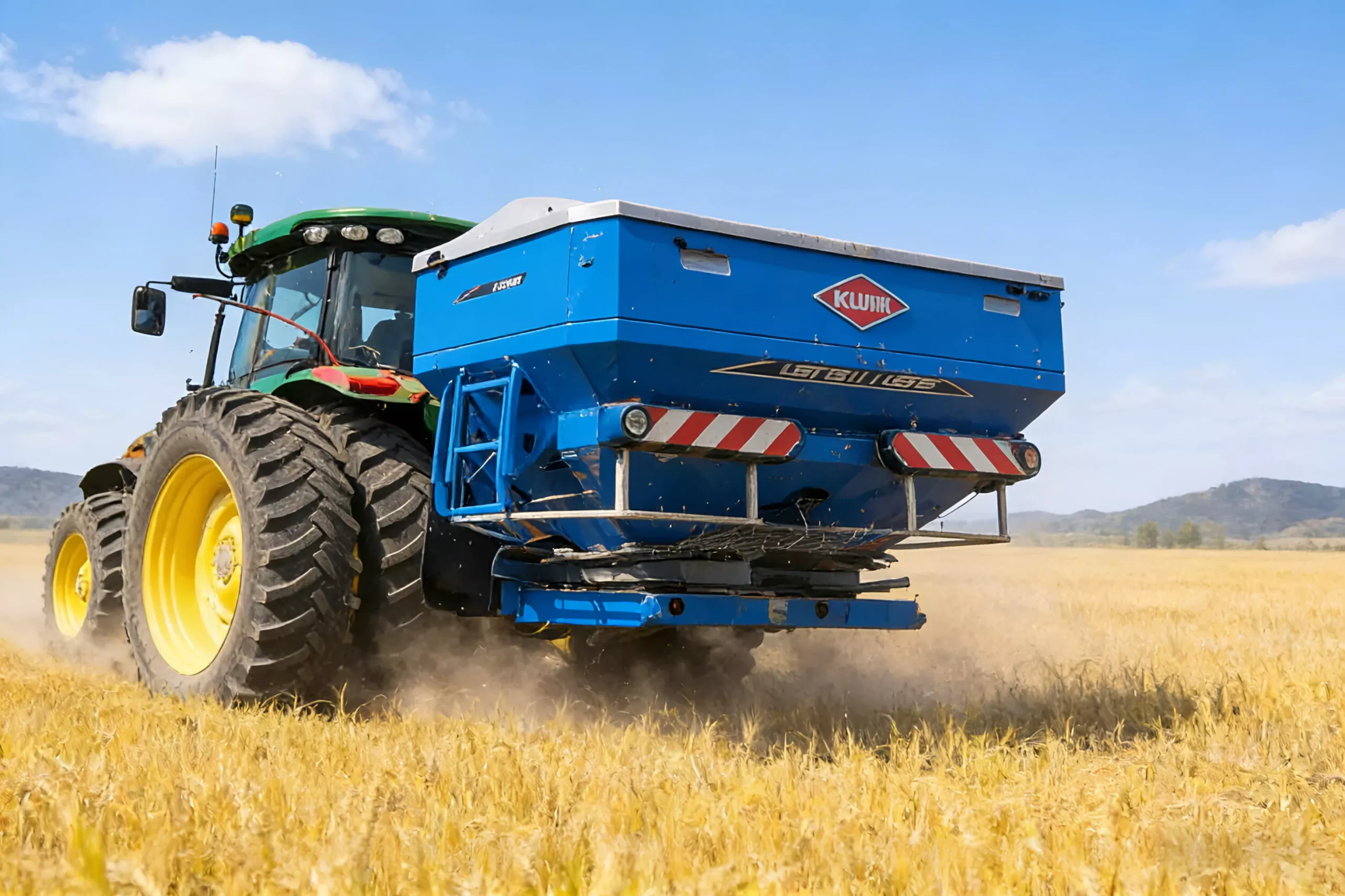
Centrifugal Spreader Gearbox Selection & Supply for Australian Farms
If you operate or build centrifugal spreader equipment in Australia, the wrong gearbox specification will cost you mid-season. This article walks through what makes a centrifugal spreader gearbox different from a generic farm gearbox, what the most common failure points look like in Australian conditions, and how to specify the right unit the first time. Particular focus is given to high disc speeds creating thrust loads that exceed standard taper-roller bearing ratings and gear noise that resonates at 1000 rpm input.
Technical Specifications & Selection Guide
Engineering Reference Specifications
The following parameters represent the typical specification range for centrifugal spreader gearboxes supplied to Australian customers. Custom configurations are available on request.
Key Parameters Table
| Parameter | Specification | Why It Matters for Centrifugal Spreader |
|---|---|---|
| Input speed | 540 rpm or 1000 rpm | Affects gear pitch-line velocity and lubrication regime |
| Ratio | 1:1.93 step-up | Matches input speed to required output rpm |
| Continuous torque | 210 Nm | Determines if gearbox can sustain continuous duty |
| Service factor | 1.5 | Critical for centrifugal spreader shock loading conditions |
| Housing material | high-pressure die-cast aluminium | Affects strength and corrosion resistance |
| Approximate weight | 8.5 kg | Affects mounting requirements and field handling |
| Shaft configuration | Solid, hollow, splined, keyed (configurable) | Must match implement coupling specification |
Step-by-Step Selection Workflow
- Confirm input speed — verify whether your tractor PTO runs at 540 rpm or 1000 rpm (or front PTO if applicable)
- Calculate required output — the implement manufacturer typically specifies the output rpm and torque required at the centrifugal spreader drive shaft
- Apply correct service factor — for centrifugal spreader duty we recommend at least 1.5 due to the loading characteristics described above
- Match shaft configuration — confirm spline pattern, key dimensions and shaft length for both input and output
- Specify mounting orientation — horizontal, vertical or angled mounting affects oil level and seal selection
- Define environmental sealing — based on dust, moisture and chemical exposure expected in your operation
- Verify lubrication compatibility — confirm recommended oil grade matches your service routine
Common Selection Mistakes to Avoid
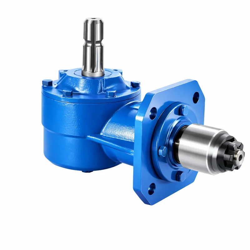
Bevel vs Worm vs Helical: Which for Centrifugal Spreader?
| Type | Best for Centrifugal Spreader? | Strengths | Weaknesses |
|---|---|---|---|
| Spiral bevel | Most centrifugal spreader duty | 90 deg power transfer, high efficiency, robust | More expensive than straight bevel |
| Worm | High-reduction holding loads | Self-locking, very high ratios, compact | Lower efficiency, generates heat |
| Helical | Inline shaft applications | Quiet operation, smooth power flow | No 90 deg deflection without bevel stage |
Not sure which model fits your specific centrifugal spreader machinery?
Real Australian Field Cases for Centrifugal Spreader Gearboxes
The following case studies are drawn from active service records of Australian customers across centrifugal spreader applications. Each illustrates a specific engineering challenge and the technical solution that resolved it. To learn more about the manufacturing capability behind these solutions, see our complete agricultural parts catalogue and capability overview.
Case 1: Parkes, NSW
Equipment: twin-spinner centrifugal spreader
Challenge: thrust bearing wear after 800 hours of high-rate spreading
Solution: upgraded to angular contact bearings with extended preload
Result: bearing service life increased to over 3,200 hours
Case 2: Naracoorte, SA
Equipment: ISOBUS centrifugal spreader
Challenge: gear noise at 1000 rpm operation indicating tooth pitting
Solution: specified ground spiral bevel gears with phosphate-treated tooth surfaces
Result: noise level dropped 6 dB and pitting eliminated
Case 3: Roma, QLD
Equipment: high-speed spinner
Challenge: spline fretting on disc output shaft
Solution: supplied output shaft with hardened spline and MoS2 grease specification
Result: no fretting observed after two full seasons
Case 4: Griffith, NSW
Equipment: pneumatic-assist centrifugal spreader
Challenge: housing fatigue cracks at mounting flange
Solution: redesigned mounting flange with reinforced gussets in casting
Result: zero crack propagation after three years field service
Case 5: Clare Valley, SA
Equipment: hopper-tipping spinner
Challenge: vibration causing premature seal wear
Solution: dynamic balance to G6.3 grade with reinforced seal carrier
Result: vibration reduced 70% and seal life doubled

Application Scenarios & Australian Pain Points
Typical Centrifugal Spreader Equipment We Supply Gearboxes For
Australian Regional Coverage
Our centrifugal spreader gearboxes are in active service across the following Australian regions, where field conditions create distinct technical demands:
Common Failure Modes in Australian Centrifugal Spreader Operations
Years of analysing returned units from Australian operators has identified these as the dominant failure modes for centrifugal spreader gearboxes:
- !thrust bearing wear from high disc speeds
- !noise increase from helical gear pitting
- !splined output coupling fretting
Need a gearbox specified to your exact centrifugal spreader equipment?
Installation & Service Routine for Centrifugal Spreader Gearboxes
Correct service routine extends centrifugal spreader gearbox life by a factor of three to five compared to neglected units. Australian operating conditions — heat, dust, abrasive soils — make adherence to the schedule below particularly important.
Step-by-Step Installation Sequence
- Verify shipping condition — confirm shaft rotation is free, check housing for transit damage and verify oil presence at the sight glass
- Confirm mounting alignment — bring the centrifugal spreader gearbox to its mating flange ensuring less than 0.10 mm radial offset from the driving shaft centre line
- Bolt to manufacturer torque — use thread-locker on mounting bolts, tighten in cross pattern to specified torque value
- Connect input PTO with verified spline match — confirm 1-3/8″ 6-spline or 1-3/4″ 20-spline matches your tractor PTO
- Install breather correctly — at the highest position with a dust filter for Australian conditions
- Check oil level cold — never fill while warm; warm oil expands and overfilling causes seal extrusion
- Run-in at idle for 5 minutes — confirm no abnormal noise, vibration or temperature rise before full centrifugal spreader loading
- Re-check oil level after first 8 hours — top up if any oil consumption observed
Lubricant Selection: EP90 vs EP140 vs Synthetic
| Grade | Best For Centrifugal Spreader Duty | Service Interval |
|---|---|---|
| EP90 GL-5 | Cool-climate centrifugal spreader duty, intermittent operation | 250 hours or annually |
| EP140 GL-5 | Hot-climate centrifugal spreader operation, sustained loading | 250 hours or seasonal |
| Synthetic SHC 220 | Continuous high-load centrifugal spreader duty, premium service life | 500 hours or 24 months |
Maintenance Calendar: Centrifugal Spreader Gearboxes
Daily Pre-Operation
Walk-around check, visual seal inspection, listen for unusual noise during PTO engagement
50-Hour Quick Check
Cold oil level, breather condition, input shaft fretting at the spline interface
250-Hour Service
Drain and refill oil, replace breather, measure input shaft axial play, inspect mounting bolts for loosening
Annual Workshop Service
Full disassembly, seal pack replacement, gear backlash check, housing inspection, repaint
Field Diagnostics for Centrifugal Spreader Operations
Why Australian Centrifugal Spreader Operators Trust Our Gearboxes
Australian Customer Feedback
“We swapped our centrifugal spreader gearbox supply across our high-speed centrifugal spreaders fleet in Northern NSW grain belt. Build quality and Australian field-spec design eliminated the seasonal failures we used to have. Engineering team understood our operating conditions immediately.”
Our manufacturing capability includes in-house forging, CNC machining, gear cutting and grinding, full heat treatment lines, and assembly cells with run-in testing. To learn more about our complete capability, please visit our company contact and capability page. Our engineering team includes qualified agricultural mechanical engineers averaging over 15 years of centrifugal spreader industry experience.
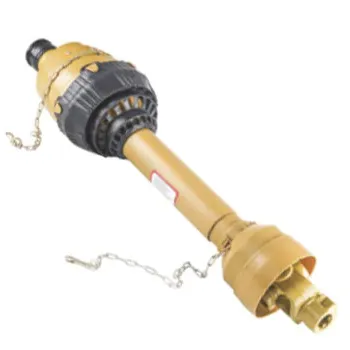
Driveline Components: PTO Shaft for Centrifugal Spreader
Many of our Australian customers source the gearbox and matched PTO shaft as a single complete driveline package. This eliminates dimensional mismatch and provides single-point warranty coverage for the entire centrifugal spreader drive system.
Frequently Asked Questions: Centrifugal Spreader Gearboxes
Below are typical questions our team receives from Australian high-speed centrifugal spreaders operators considering our centrifugal spreader gearboxes:
Next Step: Specify Your Centrifugal Spreader Gearbox
For Buyers with Specifications Ready
Send us your required ratio, mounting orientation, shaft configuration and operating conditions for your high-speed centrifugal spreaders. We respond with a written quotation and full technical data.
For Buyers Still Selecting
Send us your machinery details, photos of existing units, or part numbers. Our engineering team reviews and provides recommended specifications at no cost.
Want to evaluate a unit before committing to volume supply?
Direct contact: [email protected] · Australia-wide delivery


